
Datasheet


627
05-08-2006 SENSICK CATALOGUE
WS/WE 170
(m) 4 82610
100
10
1
1
2
3
4
WS/WE 170
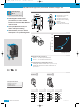
Scanning range,
max. typical
Operating
range
Operating reserve
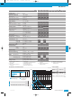
Technical data WS/WE 170-
P132 P 430 N132 N 430
Scanning range and operating reserve
Type Order no.*
6 010 181
6 010 183
6 010 182
6 010 184
Order information
* Order no. includes sender and receiver
WS
/
WE170-P132
WS
/
WE170-N132
WS
/
WE170-P 430
WS
/
WE170-N 430
1
■
Operating range
■
Scanning range,
max. typical
2
3
4
3
With slotted mask, 1 mm
4
With polarising filter and slotted mask, 1 mm
2
With polarising filter attachment
Without attachments
1
0(m) 2 4 6 8 10
8.5
07
403
1.301
0.80 0.5
Scanning range, max. typical 8.5 m
Operating range 7m
Light source
1)
, light type LED, red light
Light spot size Approx. 850 mm at 7 m
Angle of dispersion, sender Approx. 7°
Angle of dispersion, receiver Approx. 20°
Supply voltage V
S
10...30 V DC
2)
Ripple
3)
±10%
Current consumption
4)
sender ≤ 20 mA
receiver ≤ 30 mA
Switching outputs PNP, open collector: Q
NPN, open collector: Q
Output current I
A
max. 100 mA
Switching mode
Light-/dark-switch. via L/D control cable
+ V
S
= light-switching
0 V = dark-switching
Response time
5)
≤ 1.0 ms
Max. switching frequency
6)
500/s
Test input ”TE” sender OFF PNP, NPN: TE to 0 V
Connection types cable PVC, 2 m
7)
sender WS 3 x 0.18 mm
2
, l 3.8 mm
receiver WE 4 x 0.18 mm
2
, l 3.8 mm
plug M8, 4-pin
VDE protection class
8)
V
Circuit protection
9)
sender A, B
receiver A, B, C, D
Enclosure rating IP 67
Ambient temperature T
A
Operation – 25 °C...+55 °C
Storage – 40 °C...+70 °C
Weight with cable 2 m Sender: approx. 66 g
Receiver: approx. 66 g
with M8 plug, 4-pin Sender: approx. 25 g
Receiver: approx. 25 g
Housing material
Housing: stainless steel/ABS; optics: PC
1)
Average service life 100,000 h
at T
A
= +25°C
2)
Limit values
3)
May not exceed or fall short of
V
S
tolerances
4)
Without load
5)
Signal transit time with resistive load
6)
With light/dark ratio 1:1
7)
Do not bend below 0 °C
8)
Reference voltage 50 V DC
9)
A=V
S
connections reverse-polarity
protected
B = Inputs and outputs reverse-
polarity protected
C = Interference pulse suppression
D= Outputs overcurrent and short-
circuit protected
KD01_W170_en.qxd 28.07.2006 9:44 Uhr Seite 627