
Datasheet


626
WS/WE 170 Through-beam photoelectric switches, red light – DC
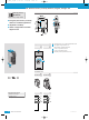
brn
blu
blk
L+
M
TE
1
L+
M
TE
NC
3
4
2
brn
blu
blk
wht
L+
M
Q
L/D
brn
blu
blk
wht
1
L+
M
Q
L/D
3
4
2
brn
blu
blk
wht
20.5
37
25.4
3.2
4
28.6
12
7. 3
16
10
3
2
1
1
0.1
Distance D
min
(mm)
110
500
100
200
300
400
0
A
B
Operating range R (m)
WS/WE 170
Minimum distance D
min.
observed for:
R 0.25 m...7 m: without optical attachments
R 0.15 m... 1 m: with slotted masks BL170-10
No mutual interference if polarising filters are used
Polarising filter attachments BL170-POLF up to R ≤ 3 m only
Polarising filter BL170-POLF and slotted masks BL170-10
up to R ≤ 0.5 m
■ Polarising filter attachments
(accessories) to reduce mutual
interference if several WS/WE 170
units are used
■ Test input (WS 170 sender) for
device and system testing
■ Slotted masks (1 mm) to detect
small parts or for positioning tasks
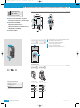
Dimensional drawing
WS
/
WE170-P132
WS
/
WE170-N132
3x0.18mm
2
Sender
4x0.18mm
2
Receiver
4-pin, M8
Sender
4-pin, M8
Receiver
WS
/
WE170-P 430
WS
/
WE170-N 430
Connection types
C R V
Mounting holes l 3 mm with
integrated M3 thread
LED signal strength indicator,
red: light received ≥ switching
threshold
Centre of optical axis,
sender (WS) and receiver (WE)
2
3
1
Minimum distance D
min.
between sides of two WS/WE 170 units
Prevention of mutual interference with two WS/WE 170 units
D
A
B
o
p
t
ic
e
le
c
tro
n
ic
o
p
t
ic
e
le
c
tr
o
n
ic
D
min.
RW
C
Scanning range
8.5 m
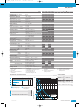
Through-beam photoelectric switches
*)
Mounting brackets included with delivery
See chapter Accessories
Cables and connectors
Mounting systems
*)
Special accessories
SENSICK CATALOGUE
05-08-2006
KD01_W170_en.qxd 28.07.2006 9:44 Uhr Seite 626