
User manual


5
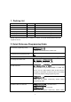
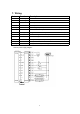
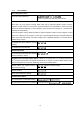
7. Wiring
Colour Function Description
Pink BELL_A Doorbell button one end
Pale blue BELL_B Doorbell button to the other end
Green D0 WG output D0
White D1 WG output D1
Grey ALARM Alarm negative(alarm positive connected 12 V+)
Yellow OPEN Exit button one end(the other end connected GND)
Brown D_IN Magnetic switch one end(the other end connected GND)
Red 12V+
12V + DC Regulated Power Input
Black GND
12V - DC Regulated Power Input
Blue NO Relay normally-on end(Connect positive electric lock "-")
Purple COM
Relay Public end, connect GND
Orange NC
Relay Closed end(connect negative electric lock "-")
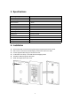
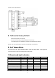
common power supply diagram: