
User's Manual

ALFOplus 24GHz (North America) - Release 01.05.0x - MN.00395.E - 004 69
8.5 GROUNDING CONNECTION
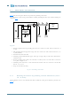
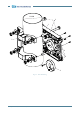
Fig.30 and annexed legend show how to perform the grounding connections.
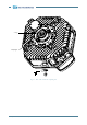
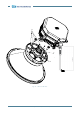
The ODU must be connected to ground with the available grounding bolt and eyelet terminal, making ref-
erence to Fig.31
.
Legend
1. Ethernet equipment chassis grounding point. The cross section area of the cable used must be 4
sq. mm.
2. ODU grounding M6 bolt copper faston type. The cross section area of the cable used must be 16
sq. mm (V42025)
3. IDU–ODU interconnection cable.
4. Grounding cable kit (ICD00072F) copper cable type or copper alloy to connect the shield of inter-
connection cable.
5. Battery grounding point of IDU to be connected to earth by means of a cable with a section area
2.5 sq. mm. Length 10 m.
6. Grounding cords connected to a real earth internal of station. The cross section area of the cable
must be 16 sq. mm
7. Surge arrester (when needed).
Fig.30 - Grounding connection
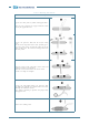
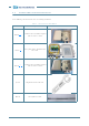
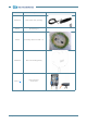
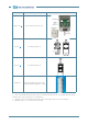
8.5.1 Mounting instructions of grounding cable kit ICD00072F (univer-
sal - no tools)
The kit IDC00072F can be used for both RG8 cable and Ethernet cable, please follow the procedure (see
Tab.11
).
Ethernet
equipment
(IDU)
ODU
unit
2
5
(+)
(-)
4
Local
ground
rack
chassis ground
Indoor
Station
ground
6
1
7
4
3