
User's Manual

60 ALFOplus 24GHz (North America) - Release 01.05.0x - MN.00395.E - 004
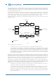
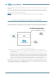
MW Adaptive Bandwidth (MAB) protocol description
The general approach to solve this problem will be through the use of a special “Ethernet Operations,
Administration and Maintenance” (E-OAM) message, which will be able to report changes in band-
width availability. Through a combination of the generation and reception of this message and the appro-
priate configuration of forwarding rules on the Cisco MWR, the ring will be able to modify the traffic profile
to take account of the degraded path.
An ITU-T Y.1731 Vendor Specific Message (VSM) is used for the purpose of reporting the currently
available bandwidth (BW) information from the Microwave radio to the Cisco MWR. This message will be
referred to thereafter as the BW-VSM.
The default settings for the protocol are the followings:
• the BW-VSM is sent untagged. However, the equipment optionally supports that the BW-VSM could
be transmitted with a configurable valid IEEE 802.1Q VLAN tag
• the BW-VSM is associated with Maintenance Level 0. However, the equipment optionally allows the
network operator to associate the message with a valid Maintenance Level in the range 0 to 7 as
per the ITU-T Y.1731 / IEEE 802.1ag-2007 standards.
Procedures on Transmitter (SIAE Microwave radio)
At steady state, and while there is no fading on the microwave link, BW-VSM messages must not be gen-
erated. Only when the radio transceiver detects degradation or subsequent improvement in the microwave
link quality and changes its modulation scheme, it must advertise the change using the BW-VSM defined
in the section above. The radio transceivers should handle on their own any fading event that lasts less
than N seconds (N= 10 or greater, may be configurable). Such short-lived events should not be reported
using BW-VSM. When the fading exceeds the N seconds threshold, the equipment must immediately gen-
erate a VSM with:
• Nominal Tx BW: set to the nominal link Tx BW, when there’s no fading
• Current Tx BW: set to the current link Tx BW
Subsequent messages must be sent periodically at the set transmission period, for the duration of the fad-
ing event. In those periodic messages, the Current Tx BW field must be set to reflect the most up to date
status of the link. This includes both the case where the link condition is deteriorating (i.e. decreasing BW)
as well as the case where it is improving (i.e. increasing BW).
When the fading subsides, the equipment must send a final BW-VSM with the Current Tx BW field set to
the nominal value. This will signal the end of the fading event.
Microwave Radio re-provisioning, equipments or cards replacement, cable re-connection must trigger a
BW-VSM message transmission, with the Current Tx BW field set to the nominal value, to re-align the sys-
tems.
Procedures on Receiver (CISCO Ethernet switch or router)
The solution enables ITU-T G.8032 Ethernet Ring Protection mechanisms to be triggered in response to
degradation in BW on the microwave link, i.e. Signal Degrade (SD) condition. The switch will be con-
figured a priori with the bandwidth threshold at which every Ethernet Ring Protection (ERP) in-
stance on the ring is to be rerouted in case of a degraded link.
As part of the network capacity planning, the operator should:
• analyze the allocation of VLANs to ERP (G.8032) instances according to the bandwidth profile
of the EVCs associated with those VLANs
• determine the failover thresholds based on the aggregate BW of the ERP instances in re-
lation to the microwave link budget at the various capacity levels associated with the adaptive mod-
ulation schemes
When a Maintenance Endpoint (MEP) on a Cisco MWR receives the first BW-VSM message reporting
degradation, it waits for a Hold-Time of N seconds before detecting the Signal Degrade (SD) defect condi-
tion where N will be configurable in 1 sec increments from 0 to 600 seconds. The purpose of this is to in-
troduce a dampening effect and ensure network stability in the case of link instability.