
User's Manual

ALFOplus 24GHz (North America) - Release 01.05.0x - MN.00395.E - 004 55
7.9.2 Service RMON
The Service RMON counters allow the equipment to track the variables listed above depending on the Ser-
vice (Vlan Tag). This type of RMON can be set only on the Radio interface.
Each equipment can be set to collect RMON up to 32 Services (Vlan Tag) and only one Customer Tag.
These counters will be available only with the Minimum Polling Policy of 15 min.
7.10 SYNCHRONISM
Network Synchronisation is a growing subject related to the network evolution from TDM to Ethernet pay-
load.
In this chapter it will be described the different features supported by SIAE switch equipment for the syn-
chronization transport. The decision of the correct source to enable and how to pass the synchronisation
signal to customer’s equipment depends on network situation which has to be evaluated case by case.
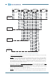
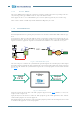
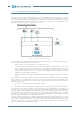
Fig.20 - NodeB and BTS synch
The main concept is to transfer the synchronization signal throughout the network deployed. This implies
that SIAE equipment will take the clock signal from the concentration points (POC) and transfer it towards
the tail sites and distribute the synchronization signal to the external equipment such as NodeBs and BTS
(see Fig.20
).
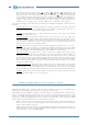
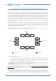
Fig.21 - SETS circuit
Going into details, this means that each SIAE equipment (represented in Fig.21
) will have, at least, one
“Input” and one “Output” CK.
Input (CK IN) is/are the interface/s where the SIAE equipment get the Clock signal from, these could be
another SIAE equipment or external equipment.
Output (CK OUT) is/are the interface/s where the SIAE equipment provides the Clock Signal to, these could
be another SIAE equipment or external equipment.
ETH
ALFOplus
ETH
Reference
Clock
SyncSync
Sync
Sync
2G BTS
3G NodeB
Full IP
Sync
ETH
ETH
Ethernet/TDM
Network
Sync
ALFOplus
ALFOplus
SETS
Input
CK IN
Output
CK OUT