
User's Manual

52 ALFOplus 24GHz (North America) - Release 01.05.0x - MN.00395.E - 004
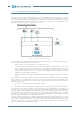
ified. Two Directions are possible, MEP “ ” and MEP “ ”. With MEP “ ” configured the OAM
PDUs are sent from the interface in the direction outside the equipment, i.e. the OAM PDUs are sent
from the interface on the cable toward next equipment. With MEP “ ” configured the OAM PDUs
are sent from the interface toward the inside of the equipment and will follow the VLAN table pre-
viously configured. MEPs are distinguished from each other through a MEP ID, therefore MEPs be-
longing to same MA must have different MEP IDs. In order to configure a MIP the MA has to be
habilitated on the equipment. Up to 32 MIPs or MEPs can be configured on each equipment.
The protocols belonging to the Connectivity Fault Management implemented in SIAE equipment are listed
hereafter:
• Continuity Check Protocol
: this protocol enables the sending of a periodic message (like a Heartbeat
message) which enables the other MEPs deployed in the network to distinguish the status of a vir-
tual connection. this message can only be originated by a MEP.
ALFOplus
: is adjustable with 1s, 10s, 1min, 10min. These messages do not trigger any automatic
reply from the destination entity.
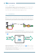
• LoopBack Protocol
: it resembles an IP PING message; once this message is sent (e.g. MEP1 sends
a Loopback Message to MEP2). MEP2 replies to MEP1 confirming therefore the status of the connec-
tion. This is done to check the status of the connection between the MEP originating the message
and the MEP/MIP to which the message is addressed. This message can only be originated from one
MEP and can be addressed to both MEPs or MIPs.
ALFOplus
: the number of Loopback Messages in SIAE equipment is adjustable from 1 to 5 consec-
utive Loopbacks. In each equipment, it is possible for each MEP to check the presence of other MEPs
in the same MA. This is done through the “Remote MEP” application which allows this acknowledge-
ment and distinguishes the other MEP through means of MEP IDs and MAC address.
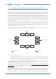
• Link Trace Protocol
: this protocol sends a message similar to the LoopBack protocol. Every equip-
ment that is reached by this message will answer to the sender providing its own MAC address. In
this way the sender is able to understand of which equipment the MA is composed. E.g. a MEP sends
the Link Trace Message to another MEP belonging to the same Maintenance Association. the MIPs
that are deployed in the middle of the path will forward this message and answer to the initiating
MEP with their own MAC Address. By doing so the initiating MEP knows the OAM-devices deployed
in the path and their order.
• Remote Defect Indicator
: this feature allows a MEP, in presence of a fault or a defect, to send a RDI
to inform the other MEPs, belonging to the same MA, of the presence of this Defect. The advantages
of this procedure are to avoid multiple Alarms created by the same cause and to be able to check
the status of other Remote MEPs. This RDI information is reported in the Continuity Check Message.
ALFOplus
: this feature is present in SIAE equipment and the presence of this alarm can be checked
as well in the Remote MEPs screen on the equipment.
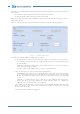
7.7 ETHERNET PERFORMANCE MONITORING - RMON
RMON (Remote Monitoring) is a standard whose function is providing a set of services of statistics count,
monitoring and alarm report with reference to the activity of a LAN network.
SIAE equipment support RMONv1, first MIB, as defined in RFC2819. This MIB contains real-time LAN sta-
tistics e.g. utilization, collisions and CRC errors. These counters are managed locally into the radio equip-
ment and are defined independently for each port of the device (both LAN and Radio interfaces). SIAE
NMS systems collect periodically this data and store it into the network database. More in details, the RMON
implementation in SIAE Network Elements is classified into two groups:
• RMON – Statistics: These are the counters data collected in real time by the Network Equipment.
These data are stored in the network equipment itself and, the NMS Statistics viewer can visualize
this data with the “Refresh” button.
• RMON - History: This is managed by the NMS through the collection of the counters data from the
Network Equipment. After a periodical polling to the Network Element, the NMS collects all the data
and these data are seen as the RMON History.