
User's Manual

38 ALFOplus 24GHz (North America) - Release 01.05.0x - MN.00395.E - 004
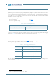
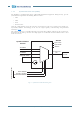
7.1.5 Synchronisation unit (SETS)
Into ALFOplus a synchronisation circuit, called SETS (Synchronous Equipment Timing Source), gets the
synchronisation signal from the following different sources:
•LAN1
•LAN2
•radio
• Internal source
From the synchronization sources the reference clock is chosen on the base of alarm roots (Synch Loss,
Synch Drift, Holdover Freerunning), on the base of assigned priority, manual forcing and preferential
switch (see Fig.9
).
The selected clock drives an oscillator through a PLL circuit. The oscillator will generate the required syn-
chronisation for the frame generation. If no input signals are available the internal oscillator source is used
for the local restart.
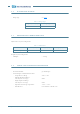
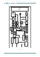
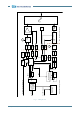
Fig.9 - Synchronisation block diagram
TE LAN-1
Clock Selector
Synchronisation
Source
TE LAN-2
T2 Radio
Internal Clock
PLL
Circuit
Sync Loss
Sync Drift
Status
T0 Reference
Clk
Alarms
Force Switch
Priority Control
Preferential Switch
Selection Logical