
User's Manual

ALFOplus 24GHz (North America) - Release 01.05.0x - MN.00395.E - 004 23
6.2 LINE INTERFACE CHARACTERISTICS
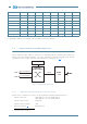
The line interfaces (LAN1, LAN2) are connected to an embedded Ethernet switch. Ethernet traffic is for-
warded to the radio interface through a 1 Gbps port, baseband and modem processing blocks. Network
synchronism can be acquired and provided by each Ethernet switch port (see Fig.5
).
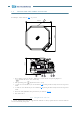
Fig.5 - ALFOplus block diagram
6.2.1 Ethernet electrical interface characteristics
All ports can be “transmitters or sources” of the synchronism through Synchronous Ethernet.
- Ethernet connectors LAN1 IEEE 802.3 10/100/1000BaseT RJ45
LAN2 IEEE 802.3 10/100/1000BaseT RJ45
- Ethernet cable category CAT5/CAT6
- Ethernet cable max length 100m
- Power over Ethernet
3
IEEE 802af PoE
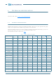
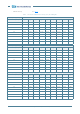
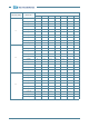
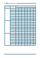
4QAM 0 8.2 10.7 2.5 17.1 4.5 19.6 4.5
16SQAM -2.5 12.6 15.1 2.5 18.9 4.5 18.9 7.0
16QAM -2.5 14.4 16.9 2.5 21.3 4.5 22.6 4.5
32QAM -3.75 16.8 19.3 2.5 24.6 4.5 24.4 5.8
64QAM -3.5 19.6 22.6 3 27.2 5.0 27.2 4.8
128QAM -3.5 22.7 25.2 2.5 30.2 4.5 30.8 4.5
256QAM -4.125 25.7 28.2 2.5 33.3 4.5 33.3 5.1
512QAM -4.25 28.8 31.3 2.5 36.5 4.5 36.5 4.6
1KQAM -4.25 32 34.5 2.5 4.5 4.5
a. Upshift thresholds in case of constant output
b. Upshift thresholds in case of output power depending on current modulation
3 Maximum power excluded.
Ethernet
packet switch
Port A
Radio
1+0
LAN1
LAN2
10/100/1000BaseT or
100/1000BaseX
10/100/1000BaseT
Microcontroller
1000BaseX