
Software Manual

122 ALFOplus 24GHz (North America) - Release 01.05.0x - MN.00395.E - 004
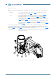
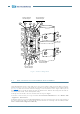
Antenna aiming
Antenna aiming devices allow to perform the following adjustments with respect to the starting aiming po-
sition:
- horizontal ± 15° operating on the nut (3) shown in Fig.91
, only after having loosen
the nuts (7), (8), (9), (10) of Fig.92
.
- vertical ± 15° operating on vertical adjustment worm screw (2) shown in Fig.91
only after having loosen nuts (1), (2), (11) of Fig.92 and (4) of Fig.91
For adjustment from 0° to +30° extract nut (1) Fig.92 and position it in
hole (4), extract nut (2) Fig.92
and position it in hole (6). Operate on
vertical adjustment worm screw (2) after having loosen nuts (1), (2), (11) of
Fig.92
and (4) of Fig.91.
For adjustment from 0° to –30° extract nut (1) of Fig.92
and position it in hole
(3), extract nut (2) of Fig.92
and position it in hole (5). Operate on vertical
adjustment worm screw (2) after having loosen nuts (1), (2), (11) of Fig.92
and (4) of Fig.91.
For vertical adjustment some markers, every 10°, are available on support. The bigger marker gives 0°
starting aiming position. Once the optimum aiming position is obtained, tighten firmly the four nuts (1),
(2), (11) of Fig.92
and (4) of Fig.91 for vertical adjustment and the four nuts (7), (8), (9), (10) of Fig.92
for horizontal adjustment. Tighten with 15 mm wrench and 32 Nm torque.
- grounding The grounding can be connected with the available bolt spring washer and
flat washers as shown.
Fig.91 - Vertical and horizontal adjustment
1
2
3
4
5