XPC User Guide For the : SA76
Shuttle® XPC Installation Guide Copyright ©2009 by Shuttle® Inc. All Rights Reserved. No part of this publication may be reproduced, transcribed, stored in a retrieval system, translated into any language, or transmitted in any form or by any means such as electronic, mechanical, magnetic, optical, chemical, photocopy, manual, or otherwise, without prior written permission from Shuttle® Inc.
Safety Information Read the following precautions before setting up a Shuttle XPC. CAUTION Incorrectly replacing the battery may damage this computer. Replace only with the same or equivalent as recommended by Shuttle. Dispose of used batteries according to the manufacturer's instructions. Laser compliance statement The optical disc drive in this PC is a laser product. The drive's classification label is located on the drive. CLASS 1 LASER PRODUCT CAUTION:INVISIBLE LASER RADIATION WHEN OPEN.
TABLE OF CONTENTS Driver and Software Installation...................................................................................1 Mainboard Driver CD ..............................................................................................1 Install Mainboard Software ..............................................................................2 Appendix......................................................................................................................3 Enter the BIOS...........
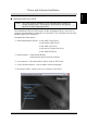
English Driver and Software Installation Motherboard Driver DVD Note : The DVD contents attached in SA76 motherboard are subject to change without notice. The product's specifications will depend upon the actually shipping product. The Motherboard Driver DVD contains all the motherboard drivers necessary to optimize the performance of this XPC in a Windows® OS. Install these drivers after installing Microsoft® Windows®.
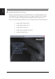
English Installing Motherboard Software Insert the attached DVD into your DVD-ROM drive. The DVD AutoRun screen should appear. If the AutoRun screen does not appear, double click on Autorun icon in My Computer to bring up Shuttle Mainboard Software Setup screen. Click the “Install Motherboard Drivers“ bar. Individually install the following drivers.
English Appendix BIOS Settings The SA76 BIOS ROM has a built-in Setup program that allows users to modify basic system configuration. This information is stored in battery-backed RAM so that it retains Setup information even if the system power is turned off.
English The Main Menu Once you enter the AwardBIOS(tm) CMOS Setup Utility, the Main Menu will appear on the screen. The Main Menu allows you to select from several setup functions and two exit choices. Use the arrow keys to select among the items and press to accept and enter the sub-menu. Note that a brief description of each highlighted selection appears at the bottom of the screen. Setup Items The main menu includes the following main setup categories.
English PnP / PCI Configurations This entry appears if your system supports PnP / PCI. PC Health Status This entry displays the current system temperature, Voltage, and FAN settings. Frequency/Voltage Control Use this menu to specify your settings for frequency/voltage control. Load Default Settings Use this menu to load the BIOS default values that are factory-set for optimal system operation.
English Standard CMOS Features The items in the Standard CMOS Setup Menu are divided into several categories. Each category includes none, one or more than one setup items. Use the arrow keys to highlight the item and then use the or keys to select the value you want in each item. Date - Set the system date. Note that the 'Day' automatically changes when you set the date. Time The time is converted based on the 24-hour military-time clock.
English Base/Extended/Total Memory Theseitems are automatically detected by the system at start up time. These are display-only fields. You can't make change to these fields. ****************************************************** IDE Adapters The IDE adapters control the hard disk drive. Use a separate sub-menu to configure each hard disk drive. IDE HDD Auto-Detection Press to auto-detect HDD on this channel. If detection is successful, it fills the remaining fields on this menu.
English Cylinder Set the number of cylinders for this hard disk. Min = 0, Max = 65535 Head Set the number of read/write heads. Min = 0, Max = 255 Precomp Warning: Setting a value of 65535 means no hard disk. Min = 0, Max = 65535 Landing zone Set the Landing zone size. Min = 0, Max = 65535 Sector Number of sector per track.
English Advanced BIOS Features This section allows you to configure your system for basic operation. You have the opportunity to select the system's default speed, boot-up sequence, keyboard operation, shadowing, and security. CPU Feature Options are in its sub-menu. Press to enter the sub-menu of detailed options. AMD Cool&Quiet control This item allows you to set the AMD Cool&Quiet control. The choice: Auto or Disabled.
English Enabled Activates automatically when the system boots up,causing a warning message to appear when anything attempts to access the boot sector or hard disk partition table. Disabled No warning message will appear when anything attempts to access the boot sector or hard disk partition table. The choice: Enabled or Disabled. Quick Power On Self Test This item speeds up Power-On Self Test (POST) after you power on the computer.
English HDD Security Freeze Lock This item allows you to enable/disable the HDD Security Freeze Lock. Enabled - prevents any external application from locking Hard drive except for BIOS. The choice: Enabled or Disabled. Delay For HDD This item allows you to set delay for HDD. The choice: 0~15. Full Screen LOGO Show This item allows you to enable/disable the Full Screen LOGO Show. The choice: Enabled or Disabled.
English Integrated Peripherals On-Chip SATA Device Option are in its sub-menu. Pressto enter the sub-menu of detailed options. OnChip SATA Channel This item allows you to enable or disable the SATA Controller. The Choice: Enabled or Disabled. OnChip SATA Type This item allows you to set the OnChip SATA Type. The choice: RAID, AHCI, Legacy IDE or Native IDE. Not support RAID 10 function in RAID mode. Onboard Devices Option are in its sub-menu.
English UMA Frame Buffer Size This item allows you to set the UMA Frame Buffer Size. The Choice: 32MB, 64MB, 128MB, 256MB or 512MB. Surround View This item allows you to set the Surround View. The Choice: Auto, Disabled or Enabled. High Definition Audio This item allows you to set the High Definition Audio. The choice: Enabled or Disabled. Onboard LAN Function Decide whether to invoke the onboard LAN chip. The choice: Enabled or Disabled.
English CIR Function This item allows you to set the CIR Function. The choice: Enabled, or Disabled. USB Device Setting Option are in its sub-menu. Pressto enter the sub-menu of detailed options. USB 2.0 Controller Enable or Disable Universal Host Controller Interfacefor Universal Serial Bus. The choice: Enabled or Disabled. USB Operation Mode Auto decide USB device operation mode. High speed: If USB device was high speed device, then it operated on high speed mode.
English Power Management Setup The Power Management Setup allows you to configure your system to most effectively saving energy while operating in a manner consistent with your own style of computer use. ACPI Function This item allows you to enable/disable the Advanced Configuration and Power Management (ACPI). Always "Enabled". ACPI Suspend Type This item allows you to select sleep state when suspend. The choice: S1(POS) or S3(STR).
English Date(of Month) Alarm This item selects the alarm Date (day of the month). Key in a DEC number: Min=0, Max=31. Time(hh : mm : ss) Alarm This item selects the alarm Time. [hh] Key in a DEC number: Min=0, Max=23. [mm/ss] Key in a DEC number: Min=0, Max=59. Power on By PS2 Keyboard This item allows you to set the Keyboard Power On function. Only supports S4/S5. The choice: Disabled, password, Hot KEY, Any KEY. KB Power ON Password This item allows you to set the KB Power On Password.
English PnP/PCI Configurations This section describes the configuration of PCI bus system. PCI or Personal Computer Interconnection is a system which allows I/O devices to operate at the speed CPU itself keeps when CPU communicating with its own special components. This section covers some very technical items, and it is strongly recom-mended that only experienced users should make any changes to the default settings.
English PC Health Status CPU Fan Speed Control Here you can set the CPU Fan Speed. The choice: Smart Fan Mode, Ultra-Low Speed, Low Speed, Mid Speed, or Full Speed. CPU Voltage +5V +3.3V +12V DDR2 Voltage ChipSet Voltage +5VSB Voltage Battery System Temperature CPU Temperature Fan 2 - Chipset Fan Fan 1 - CPU Fan 18 Before manually modifying the CPU fan setting, please make sure fan connectors are plug ged into the correct fan conne ctor on the motherboard.
English Frequency/Voltage Control HT Link Width This item allows you to enable or disable the HT Link Width. The choice: Auto, 8 bit or 16 bit. HT Link Frequency This item allows you to set the HT Link Frequency. The choice: Auto, 200 MHz~2.6 GHz. ******** Memory Timing Set ********* Timing Mode Auto, no user limit MaxMemClk, limit by Memory Clock value. The Choice: Manual or Auto. Memory Clock Value Setting platform Memclock. The Choice: DDR533, DDR667 or DDR800.
English (Trcd)RAS to CAS R/W Delay The Choice: 3~6 clocks. (Trp)Row Precharge Time The Choice: 3~6 clocks. (Tras)Minimum RAS Active T The Choice: 5~18 bus clocks. ************** Voltage ************* Over voltage may destroy the devices like CPU, DRAM or Chipset!! CPU Voltage Offset This item allows you to set the DDR2 Voltage. The choice: Auto, +50mv~+400mv. DDR2 Voltage Set This item allows you to set the DDR2 Voltage. The choice: Auto, 1.825V~2.400V.
English Load Default Settings When you press on this item, you will get a confirmation dialog box with a message similar to: Load Default Settings (Y/N) ? N Pressing 'Y' loads the default values that are factory-set for optimal performance system operation. Set Supervisor/User Password Steps to set supervisor/user password are described as follows: New Password Setting: 1. While pressing to set a password, a dialog box appears to ask you enter a password. 2. Key in a new password.
English Save & Exit Setup Pressing on this item asks for confirmation: SAVE to CMOS and EXIT (Y/N)? Y Pressing "Y" stores the selections made in the menus of CMOS - a special section of memory that stays on after you turn your system off. The next time you boot your computer, the BIOS configures your system according to the Setup selections stored in CMOS. After saving the values the system is restarted again.