
User's Manual
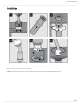
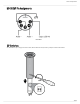


Table Of Contents

Shure Incorporated
13/25
Switch Down (default) Up
1 Full frequency response Low cut filter
2 LED steady LED flashes
LED Logic
To operate the LED indicator, use the included 5-pin XLR connector to wire the microphone to an automatic mixer or other logic
device.
Note: Connect the LED IN to the gate output to illuminate the LED when the channel is gated on.
Do not use the relay ports on Crestron and AMX devices. Use the I/O logic ports instead.
The LED logic may not function when connecting to devices that do not have internal "pull-up resistor" logic circuits, such as
ClearOne DSP products. External pullup resistor circuits can be added for each microphone. Visit www.shure.com/FAQ for de
tailed instructions.
Logic Connection
Connection to device with internal "pull-up resistor" logic circuit
MX405, 410, 415
Logic LOW (0 V) Logic HIGH (+5 V)