
Service manual
Shure LX2 Hand-Held Transmitter
Bench Checks33
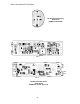
25D1006 (CG)
n If the power is slightly low and the spurious level is high, check
for wrong or open coils at L202, L210, and L206.
Note: In addition to the frequency determining components discussed
above, bypass capacitors can affect the tuning and power gain of rf
stages. Emitter bypass capacitors C226 and C223 can be probed with
the FET probe. If the rf level measured on each side of the part is not
comparable, a defective capacitor is indicated. The bypasses on the
collector circuits C207 and C208 can be checked in the same way.
Euro (ETSI)
n The output of the transmitter should be terminated in a 50 Ω load
from TP6 to ground during testing. If the unit is being tested as a
two board assembly with the rf and audio boards soldered
together, temporarily remove C242 to disconnect the battery
antenna.
n Probe the output after the oscillator stage (TP5). If there is none,
refer back to the “Distortion” section.
n Make sure that when C214 is rotated 360 degrees, two separate
peaks in the carrier output amplitude are produced. If there is
only one peak, make sure the C214 is the correct value. Check
values of L202, C208, C244, C210, L203, C213, and C215; and
check bias on Q201. Last of all, replace Q201.
n Repeat the procedure for the next rf stage. C222 should also be
turned one complete rotation to check for two peaks in the output
power. If only one peak is observed, make sure that C222 is the
correct value. Check values of L204, C216, C245, C219, L205,
C221, and C224; and check bias on Q202. Last of all, replace
Q202.
n Repeat the procedure for the third rf stage. C226 should also be
turned one complete rotation to check for two peaks in the output
power. If only one peak is observed, make sure that C226 is the
correct value. Check values of L206, C227, C229, L207, C230,
and C232; and check bias on Q203. Last of all, replace Q203.
n Repeat the procedure for the last rf power amp stage. Check the
dc bias on Q204 and values of all parts from the base of Q204 to
TP6. Last of all, replace Q204.
n If the power is slightly low and the spurious level is high, check
for wrong or open coils at L205, L207, and L210.
Note: In addition to the frequency determining components discussed
above, bypass capacitors can affect the tuning and power gain of rf
stages. Collector bypass capacitors C220 C227, and C234 can be
probed with the FET probe. If the rf level measured on each side of the
part is not comparable, a defective capacitor is indicated. The bypasses
on the collector of Q203 (C228) can be checked in the same way. Also,
the rf level measured with the FET probe should drop approximately 10
dB from the collector of one transistor to the base of the next transistor.
If the drop is higher than 12 dB, thoroughly check the stage with the
excessive loss in power.