
Service manual
Shure LX2 Hand-Held Transmitter
32
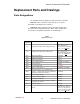
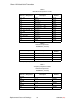
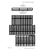
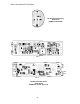
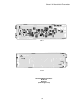
Bench Checks
25D1006 (CG)
RF Problems: Deviation
Domestic (FCC/IC)
n There must be a good carrier to get any deviation.
n If R217 cannot be adjusted to obtain 15 kHz deviation, try to iso-
late the problem to the audio or rf section. Check for –2.2 dBv at
I118; if not, refer to the Audio section of the circuit description.
n If the level is correct at I118, check R217, C220, C227, R208,
R216, D201, L209, and C214. The value of C214 is critical to
the deviation sensitivity.
n Last of all, try replacing D201 and Y201.
Euro (ETSI)
n There must be a good carrier to get any deviation.
n If R201 cannot be adjusted to obtain 15 kHz deviation, try to iso-
late the problem to the audio or rf section. Check for –2.2 dBv at
I118; if not, refer to the Audio section of the circuit description.
n If the level is correct at I118, check R201, C201, C202, R202,
R203, D201, L201, and C203. The cathode of D201 should be
getting 5.0 Vdc bias from the 5.0 Vdc line through R202 and
R203. The value of C203 is critical to the deviation sensitivity.
n Last of all, try replacing D201 and Y201.
Low Output Power
Domestic (FCC/IC)
n The output of the transmitter should be terminated in a 50 Ω load
from I210 to ground during testing. If the unit is being tested as
a two board assembly with the rf and audio boards soldered
together, temporarily remove C240 to disconnect the battery
antenna. The rf levels shown on the schematic were measured
with a FET probe without an rf ground and are only approximate.
n Probe the output after the oscillator stage (I230). If there is
none, refer back to the “Distortion” section.
n Make sure that when C217 is rotated 360 degrees, two separate
peaks in the carrier output amplitude are produced. If there is
only one peak, make sure the C217 is the correct color (value).
Check values of L205, C225, C234, L202, C233; and check bias
on Q201. Last of all, replace Q201.
n Repeat the procedure for the second rf stage. C216 should also
be turned one complete rotation to check for two peaks in the
output power. If only one peak is observed, make sure that
C216 is the correct color (value). Check values of L204, C238,
C236, L210, C235, C222, C226; and check bias on Q203. Last
of all, replace Q203.
n Repeat the procedure for the last rf power amp stage. Check the
dc bias on Q204 and values of all parts from the base of Q204 to
I210. Last of all, replace Q204.