
Service manual
Shure LX2 Hand-Held Transmitter
Bench Checks31
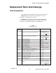
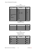
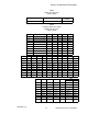
25D1006 (CG)
Audio
Loss
n Make sure mic switch is ON.
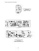
n Determine where the signal is being lost. Verify audio at U102,
pin 7. Then check dc bias at U102, pins 5, 6, and 7. They
should be about half of the supply voltage, or around 4.5 Vdc.
This bias comes from the 9.0 Vdc line through voltage divider
R103/R105, then through R106 to pin 5.
n Look for open vias, foil shorts, incorrect parts, and bad connec-
tions.
n If there is audio at pin 7, but not at pin 14, check again for db
bias.
n Pins 12 and 13 should read approximately 1.8 Vdc, while pin 14
should read about 3.7 Vdc. Dc bias comes from U101, pin 9,
through R107 to U102, pin 12.
n Next, check parts in the feedback path from pin 14 to pin 13,
parts connected to pin 7, and connections from U102 to U101.
Also check the connections from U102, pin 14, to the next stage
and to the limiter (Q103), and U101, pin 15.
n The last stage is to check U102, pins 8, 9, and 10. Dc bias
should be about 4.0 Vdc for all three pins. Dc bias comes from
the 5.0 Vdc line through R104 to U102, pin 10. Check values in
feedback from pin 8 to pin 9, and the path to Q104 and Q101,
pin 16.
Distortion
n Make sure the analyzer’s 400 Hz high pass and 30 kHz low pass
filters are in. U101, pin 9, should read about 1.8 Vdc.
n The dc level on the wiper of R130 should change from about 1.5
Vdc to 3.5 Vdc when you turn R130. If not, check, R129, C125,
R141, R140, R126, and the parts tied to U101, pin 9. Make sure
the audio level is correct.
n Last of all, try replacing D201 and Y201.