
Service manual

Shure LX2 Hand-Held Transmitter
Service Procedures27
25D1006 (CG)
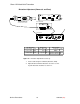
Deviation Adjustment (Domestic and Euro)
AUDIO ANALYZER
12.5 – 18.9 VDC
ANTANT
OUTPUTS
HI Z
BAL
MIC LINE
POWER
AB
LX4 RECEIVER
TRANSMITTER SHOWN WITH
BATTERY CUP REMOVED, AND
AUDIO TEST HEAD ATTACHED.
+
–
J201
J202
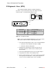
RF BOARD (TOP)
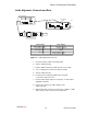
ETSI
L201
R217
Y201
C214
C216
C222
C226
+
–
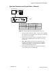
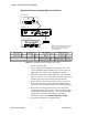
RF BOARD (TOP)
DOMESTIC
L209
R217
Y201
C217
C216
C240
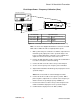
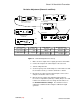
J102
J101
I210
I2GN
–
+
R130
R125
U102
U101
S102
S101
C107
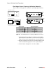
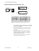
LX2 Transmitter LX4 Receiver Audio Analyzer Rf Signal Generator
Power supply: 9 Vdc Power switch: ON Frequency: 1 kHz Frequency: carrier
Power switch: PWR Gain: Max Filters: Modulation: FM
Mute switch: ON Squelch: Mid Low-Pass (30 kHz): ON Modulation source: 1 kHz
High-Pass (400 Hz): ON Rf output: OFF
Figure 18. Deviation Adjustment Test Set-Up
1. Make sure the rf output on the rf signal generator is turned OFF.
2. Connect the output of the audio analyzer to the test head.
3. Turn the LX2 power ON.
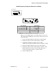
4. Set the frequency of the audio analyzer to 1 kHz. Make sure that
the level at the anode (+) of C107 is still 0.775 V ± 50 mV.
5. Disconnect any cables from the antenna inputs of the receiver
and place an antenna on the receiver.
6. Measure the rms voltage at the unbalanced Hi-Z output of
the receiver. Adjust R217 (domestic) or R201 (Euro) to 0 ± 1 dB
relative to the deviation reference voltage measured above as
the Deviation Reference Voltage. The deviation reference
voltage was established earlier using the calibrated rf signal
generator.