
Service manual

Shure LX2 Hand-Held Transmitter
26
Service Procedures
25D1006 (CG)
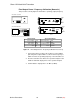
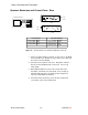
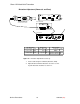
Deviation Reference Voltage (Domestic and Euro)
AUDIO ANALYZER
RF SIGNAL GENERATOR
12.5 – 18.9 VDC
ANTANT
OUTPUTS
HI Z
BAL
MIC LINE
POWER
AB
LX4 RECEIVER
NOTE: DC VOLTAGES ARE PRESENT AT MOST
RF TEST POINTS. USE A DC BLOCK ON THE
RF SIGNAL GENERATOR TO PROTECT
TEST EQUIPMENT.
DC BLOCK
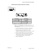
LX2 Transmitter LX4 Receiver Audio Analyzer Rf Signal Generator
Power switch: OFF Power switch: ON Frequency: 1 kHz Frequency: carrier
Mute switch: ON Gain: Max Filters: Modulation: FM
Squelch: Mid Low-Pass (30 kHz): ON Modulation source: 1 kHz
High-Pass (400 Hz): ON Output amplitude: –38 dBm
Figure 17. Deviation Reference Voltage Test Set-Up
1. Turn the LX2 power OFF.
2. Set the rf signal generator with the frequency the same as the
carrier, modulation at FM, modulation source at INT 1 kHz, the
FM deviation at ± 15 kHz, and the amplitude at –38 dBm.
3. Connect the output of the rf signal generator to either antenna
input of a receiver. Use a receiver that is the same frequency as
the LX2, such as the LX3 or LX4 that came with the LX2.
4. Set the volume control on the front panel of the receiver to the
maximum position (full clockwise rotation) and apply power to
the receiver. Set the squelch control of the receiver at midrange.
5. Measure the rms voltage developed across the Hi-Z output,
terminated in 3.3 kΩ, of the receiver. The measured rms voltage
should be approximately 0.389 V rms. This is the audio output
voltage that corresponds to a deviation level of 15 kHz.
Record this voltage as the Deviation Reference Voltage.
6. Turn off the rf output on the rf signal generator.