
Service manual

Shure LX2 Hand-Held Transmitter
Service Procedures23
25D1006 (CG)
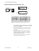
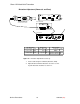
Final Output Power / Frequency Calibration (Euro)
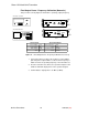
SPECTRUM ANALYZER
FREQUENCY COUNTER
CH 2
CH 1
+
–
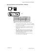
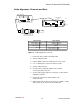
RF BOARD (TOP)
ETSI
L201
Y201
R217
C214
C216
C222
C226
J201
J202
TP7
TP6
TP5
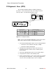
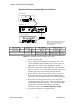
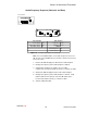
LX2 Transmitter Spectrum Analyzer
Power source: 9 Vdc Center frequency: 1/3 of the transmitter freq
Power switch: PWR Span: 30 MHz
Mute switch: MUTE Reference level: + 20 dBm
Scale: 10 dB/div
Figure 14. Final Output Power / Frequency Calibration Test Set-Up
Note: See the Service Equipment Manual for conversion of a 50 Ω
BNC cable–to–RGU174 cable to a high impedance probe.
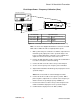
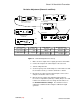
1. With a yellow Toray non-conductive screwdriver, adjust C214 for
maximum (peak) output power on the spectrum analyzer. For
better resolution while tuning, switch the scale to 2 dB/div and
adjust the reference level to the center of the screen.
2. Remove the high-impedance probe. Connect the standard 50 Ω
test cable to TP6 (before antenna-matching).
3. Connect the BNC end of the cable to the spectrum analyzer.
4. Set the center frequency to the frequency of the transmitter.
5. Adjust C216 and C222 for maximum (peak) output power on the
spectrum analyzer.
Note: C216 is not tunable on earlier ETSI-approved units.
6. Connect the 50 Ω test cable to the frequency counter. With a
pink Toray driver, adjust L201 to set the RF carrier frequency to
within ±1 KHz of the operating frequency UNDER test.
7. Reconnect the 50 Ω test cable to the spectrum analyzer. Peak
C226 for maximum output power on the spectrum analyzer.
8. Confirm that the output power is 9.5 dBm (±2 dBm).