
Service manual
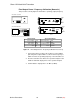

Shure LX2 Hand-Held Transmitter
22
Service Procedures
25D1006 (CG)
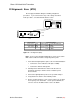
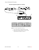
Rf Alignment: Euro (ETSI)
Do not apply modulation during the following rf alignment
procedures. If you cannot achieve any of the settings described
in this procedure, consult the Bench Checks section.
SPECTRUM ANALYZER
+
–
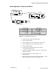
RF BOARD (TOP)
ETSI
L201
Y201
R217
C214
C216
C222
C226
J201
J202
TP7
TP6
TP5
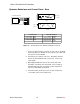
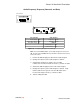
LX2 Transmitter Spectrum Analyzer
Power source: 9 Vdc Center frequency: 1/3 of the transmitter freq
Power switch: PWR Span: 30 MHz
Mute switch: MUTE Reference level: + 20 dBm
Scale: 10 dB/div
Figure 13. Rf Alignment (Euro)
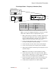
Note: See the Service Equipment Manual for conversion of a 50 Ω
BNC cable–to–RGU174 cable to a high impedance probe.
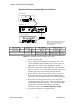
1. Tack-solder the high-impedance probe to the rf circuit board bottom:
S Connect the center conductor to TP5 (base of Q202).
S Connect the shield to circuit ground.
2. Carefully remove C242 from the rf board. This disconnects
the battery (antenna) to allow accurate conductive-power
measurements.
3. Connect the high-impedance probe to the spectrum analyzer.
4. Verify that the mic switch is in the MUTE position.
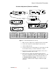
5. On the spectrum analyzer, set the center frequency to one-third
the frequency of the transmitter. Set the span to 30 MHz, the
reference level to +20 dBm, and the scale to 10 dB/div.