
Service manual

Shure LX2 Hand-Held Transmitter
20
Service Procedures
25D1006 (CG)
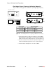
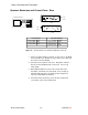
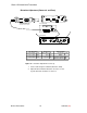
Final Output Power / Frequency Calibration (Domestic)
This procedure correctly aligns the transmitter’s operating (output) frequency.
SPECTRUM ANALYZER
FREQUENCY COUNTER
CH 2
CH 1
+
–
J101
J102
L209
R217
Y201
C217
C216
+
–
J101
J102
Y201
L201
R201
C214
C222
C226
C216
I210
I2GN
C240
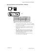
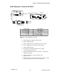
RF BOARD
SIDE 1
RF BOARD
SIDE 2
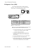
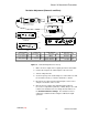
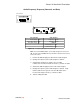
LX2 Transmitter
Spectrum Analyzer
Power supply: 9 Vdc Carrier frequency: carrier
Power switch: PWR Span: 1 MHz
Mute switch: MUTE Reference level: + 20 dBm
Gain: Mid Scale: 10 dB/div
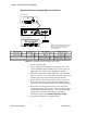
Figure 11. Final Output Power / Frequency Calibration Test Set-Up
1. Connect the 50 Ω test cable to the frequency counter. With a
pink Toray driver, adjust L209 to set the rf carrier frequency to
within ±1 kHz of the operating frequency of the unit under test.
2. Reconnect the 50 Ω test cable to the spectrum analyzer. Peak
C226 for maximum output power on the spectrum analyzer.
3. Confirm that the output power is 15 dBm (±2 dBm).