
Service manual
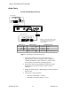

Shure LX2 Hand-Held Transmitter
Service Procedures19
25D1006 (CG)
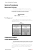
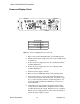
Rf Alignment: Domestic (FCC/IC)
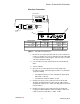
During rf alignment, the transmitter output is terminated in a 50 Ω,
nonreactive load RG174 cable and monitored with a spectrum analyzer.
No modulation is applied during rf alignment.
SPECTRUM ANALYZER
+
–
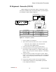
RF BOARD (TOP)
L209
R217
Y201
C217
C216
C240
J102
J101
I210
I2GN
FREQUENCY COUNTER
CH 2
CH 1
LX2 Transmitter Spectrum Analyzer
Power supply: 9 Vdc Center frequency: carrier
Power switch: PWR Span: 1 MHz
Mute switch: MUTE Reference level: + 20 dBm
Scale: 10 dB/div
Figure 10. Rf Alignment (FCC/IC)
1. Remove C240 on rf circuit board.
2. Tack-solder the 50 Ω test cable to side 1 of the rf circuit board:
S Connect the center conductor to the solder pad, I210.
S Connect the shield to I2GN (ground).
3. Connect the 50 Ω test cable to the spectrum analyzer.
4. Peak C216 and C217 for maximum output power on the spec-
trum analyzer. Output should be 15 ± 2 dBm, including cable
losses. If the correct power cannot be attained, see the Bench
Checks section.
5. Connect the 50 Ω test cable to the frequency counter. Adjust
L209 to set the carrier frequency to within ± 1 kHz of designated
value. If correct frequency cannot be attained, see the Bench
Checks section.
6. Reconnect the 50 Ω test cable to the spectrum analyzer.
7. Confirm that the output power remained within specification.
If not, readjust C216 and C217.