
Service manual

Shure LX2 Hand-Held Transmitter
Service Procedures17
25D1006 (CG)
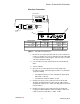
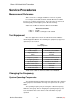
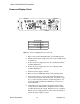
Alignment
AUDIO ANALYZER
+
–
RF BOARD (TOP)
L209
R217
Y201
C217
C216
C240
J102
J101
I210
I2GN
NOTE: Whenever soldering is performed on the
curcuit boards, always power off the unit.
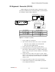
LX2 Transmitter Audio Analyzer
Power supply: 9 Vdc Filters:
Power switch: PWR 400 Hz High-Pass: ON
Mic switch: MUTE 30 kHz Low-Pass: ON
Gain: Mid
Figure 8. Rf Alignment Test Set-Up (Domestic)
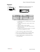
S The alignment procedure is sequential and does not change,
unless specified.
S Use RG58 or any other low-loss, 50 Ω test cables for all rf
connections.
S Keep the test cables as short as possible.
S Include the insertion loss of the cables and the connectors
for all rf measurements.
S Dc voltages are present at most rf test points. Use dc blocks
to protect the test equipment, if necessary.
1. Connect a 9 Vdc power supply to the battery terminals.
2. Make sure the mic ON/MUTE switch is in the MUTE position.
3. Set the audio gain potentiometer (R125) at mid-range.
4. Activate the 400 Hz high-pass and 30 kHz low-pass filters
on the audio analyzer.