
Service manual
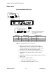

Shure LX2 Hand-Held Transmitter
10
Preliminary Tests
25D1006 (CG)
Audio Tests
Check the Matching Receiver
AUDIO ANALYZER
RF SIGNAL GENERATOR
12.5 – 18.9 VDC
ANTANT
OUTPUTS
HI Z
BAL
MIC LINE
POWER
AB
LX4 RECEIVER
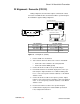
NOTE: DC VOLTAGES ARE PRESENT AT MOST
RF TEST POINTS. USE A DC BLOCK ON THE
RF SIGNAL GENERATOR TO PROTECT
TEST EQUIPMENT.
DC BLOCK
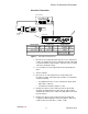
LX4 Receiver Audio Analyzer Rf Signal Generator
Power switch: ON Frequency: 1 kHz Amplitude: –20 dBm
Gain: Max Filters: Modulation:: 1 kHz
Squelch: Mid Low-Pass (30 kHz): ON Deviation: 15 kHz
High-Pass (400 Hz): ON Frequency: LX2 operating frequency
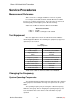
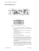
Figure 4. Matching Receiver Functional Test
1. Connect the matching receiver’s antenna input to the rf
signal generator. Set the rf signal generator’s amplitude to
–20 dBm, modulation to 1 kHz, deviation to 15 kHz, and set
the frequency to the LX2 unit’s operating frequency.
2. Connect the audio from the unbalanced output to the audio
analyzer with a 3.3 kΩ load. Turn the volume control to
maximum.
3. Engage the audio analyzer’s 400 Hz high-pass filter and 30 kHz
low-pass filter..
4. For the LX4, verify the following:
S audio level is 400 mVrms ("90 mV)
S total harmonic distortion (THD) is < 0.75%