Shure Brothers Incorporated 222 Hartrey Avenue Evanston IL 60202-3696 U.S.A. Model SCM410/SCM410E User Guide SCM410/SCM410E FOUR CHANNEL AUTOMATIC MICROPHONE MIXER 1999, Shure Brothers Incorporated 27A8690 (SG) U.S. Patents 4,658,425; 5,297,210 Printed in U.S.A.
TABLE OF CONTENTS DESCRIPTION . . . . . . . . . . . . . . . . . . . . . . . . . . . . . . . . . . . . . . . . . . . . . . . . . . . . . . . . . . . . . . . . . . . . . . . . . . . . . . . . . . . . . . . . . . . . . . 3 FEATURES . . . . . . . . . . . . . . . . . . . . . . . . . . . . . . . . . . . . . . . . . . . . . . . . . . . . . . . . . . . . . . . . . . . . . . . . . . . . . . . . . . . . . . . . . . . . . . 3 OPERATING PRINCIPLES . . . . . . . . . . . . . . . . . . . . . . . . . . . . . . . . . . . .
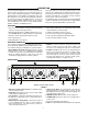
DESCRIPTION Each input channel has a two-band equalizer and three logic terminals. The equalizer reduces unwanted low-frequency audio pickup and makes different microphone types—lavaliers, boundary and handheld—sound similar. The logic terminals can be used to control external devices. The Shure Model SCM410/E is a four-channel automatic microphone mixer designed for use in sound reinforcement, audio recording, and broadcast applications.
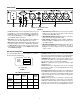
REAR PANEL MODEL SCM410 REAR PANEL FIGURE 2 1. Power Connector: Unit is energized when the power cord is plugged into a 100–120 Vac (SCM410) or 220–240 Vac (SCM410E) power source. Can be internally modified.Refer to the “Internal Modification” section. NOTE: There is no power On/Off switch on this mixer. 4. AUX OUT Phono Connector: Feeds consumer-level audio equipment, such as a tape recorder, VCR, or video camera. Not affected by MIC/LINE switch. 2.
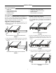
INSTALLATION SUPPLIED HARDWARE 4 rubber feet 1 rackmount bracket, long 1 rackmount bracket, short 2 straddle brackets 10 bracket screws, 6 mm (1/4 in.) 4 rackmount screws, 2.54 cm (1 in.) 4 plastic washers 4 wood screws, 1.25 cm (1/2 in.) RACK MOUNTING The SCM410 is supplied with hardware for mounting one or two units to a 19-inch audio equipment rack. The hardware can also be used to rack mount other Shure products, including the SCM268, SCM262, DFR11EQ, and the DP11EQ.
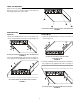
TABLE-TOP MOUNTING Adhere the four (4) supplied rubber feet to the bottom of the mixer at each corner, as shown in Figure 9. This will keep it from sliding and protect the table surface. ATTACHING RUBBER FEET FOR TABLE–TOP MOUNTING FIGURE 9 FIXED MOUNTING Top Mount Hanging Mount 1. Fasten the straddle brackets to the recessed edges of the chassis, using four (4) bracket screws, as shown in Figure 10. 1. Fasten the straddle brackets to the top of the mixer, as shown in Figure 12.
SCM410 CONNECTIONS 3. Connect the SCM410 Mic/Line Level Output to the input of mixers, EQs, amplifiers or recorders. 1. Connect microphone signal sources to the Channel Input connectors, as shown in Figure 14. Use conventional 2-conductor shielded audio cables. 4. Connect the power cord to 100–120 Vac (SCM410) or 220–240 Vac (SCM410E). 2. If any condenser microphones are connected, set the +12V phantom power DIP switch to ON.
BASIC MIXER OPERATION 3. Adjust the Master level control for the required output level, as indicated by the output peak meter. The SCM410 is now ready for use. 1. Adjust each channel level so that its Overload LED flickers only during very loud speech or noise. 2. Adjust the Low-Cut and High-Frequency controls adjacent to each Input Gain control so that the microphones sound similar.
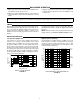
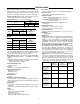
SPECIFICATIONS Measurement Conditions (unless otherwise specified): Line voltage 120 Vac, 60 Hz (SCM410) or 230 Vac, 50 Hz (SCM410E); full gain; 1 kHz, one channel activated; source impedances: Mic 150 Ω; terminations: Line/Mic Aux 10 kΩ Input LEDs Green on channel activation, red at 6 dB below clipping Phantom Power 12 Vdc open-circuit through 680 Ω resistors Operating Voltage SCM410: 100–120 Vac rated nominal, 50/60 Hz, 100 mA (maximum) SCM410E; 220-240 Vac rated niminal, 50/60 Hz, 50 mA (maximum) Mains
Replacement Parts Knob, Master (white) . . . . . . . . . . . . . . . . . . . . . . . 95A8238 Knob, Channel Gain (blue) . . . . . . . . . . . . . . . . . 95B8238 Line (Power) Cord (SCM410) . . . . . . . . . . . . . . . 95A8762 Line (Power) Cord (SCM410E) . . . . . . . . . . . . . . 95A8778 Link Cable . . . . . . . . . . . . . . . . . . . . . . . . . . . . . . . . 95A8889 Fuse, SCM410 (5 x 20 mm, T 125mA L, 250V, time delay) . . . 80C730 Fuse, SCM410E (5 x 20 mm, T 50mA L, 250V, time lag) . . . . . .
ADVANCED FUNCTIONS CAUTION: Use of Advanced Functions is recommended only for qualified audio technicians. LOGIC CONNECTION SPECIFICATIONS The SCM410 logic functions expand the range of installation and control options. Logic can be used for everything from simple cough switches to elaborate computer-controlled room systems. (Shure’s AMS Update publication contains additional applications of advanced logic. This publication is available by contacting the Shure Applications Department.
SUGGESTED LOGIC APPLICATIONS This section contains suggestions on the uses of the SCM410’s logic capabilities. Note that uses of these functions are not limited to the listed applications. The user is limited only by imagination and creativity. For additional suggestions and solutions to installation problems, contact the Shure Applications Department. Remote Channel-On Indicators Remote indicators can be used to indicate when a talker’s microphone is on.
Inhibiting Gating for Unwanted Sounds D = 1N4148 MaxBus attempts to activate only one microphone per sound source. Muting a microphone channel prevents its audio from appearing at the mixer’s output. However, the muted microphone still communicates with other mic channels via MaxBus. A sound source picked up by a muted microphone will not activate other microphones.
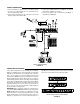
Inhibit Function External Logic Devices For information on the inhibit function, refer to the Internal Modifications section. SCM410 logic levels are directly compatible with TTL and 5V CMOS logic families. Mixer logic may be used with 15V CMOS logic if a pull-up resistor is used with each GATE output. See Figure 28. Remote Volume Control The level of the Aux or Master output can be controlled from an external VCA (Voltage Controlled Amplifier) such as the RUVCA1 from Radio Design Labs (Tel.
INTERNAL MODIFICATIONS • For Channel modifications, the first character of the refer- WARNING: Voltages in this equipment are hazardous to life. No user-serviceable parts inside. Refer all servicing to qualified service personnel. ence designator indicates the channel number,(i.e., R1027 refers to a Channel 1 resistor, X2001 refers to a Channel 2 jumper, etc.). Modifications affecting the Master section are preceded by a “9” (i.e., X9001). NOTE: • Only make changes to jumpers (X) and resistors (R).
INSERTING AN INPUT LINE PAD To insert a 40 dB line pad for a given microphone input, remove the resistors specified in the following table. Channel Remove Resistor 1 R1005, R1006 2 R2005, R2006 3 R3005, R3006 4 R4005, R4006 DISABLING THE MASTER LEVEL CONTROL Procedure: 1. Remove resistor R9203. 2. Install new resistor at jumper R9173. The Master gain control can be disabled to prevent tampering. Refer to the following table for gain levels and resistor values.
Procedure: When both MUTE IN and OVERRIDE IN logic are grounded, the Override mode will take precedence (as supplied, the MUTE IN takes precedence over OVERRIDE IN). 1. Short jumper X1005. 2. Remove resistor R1087. DEAD ZONE ON MUTE IN DEFEAT Procedure: Short jumper X1002. As supplied, MUTE IN is intended for use as a momentary cough button or privacy function (mute when necessary).
Procedure: Short jumper X1003. This modification is equivalent to shorting one of the channel OVERRIDE IN to the LOGIC GROUND pin via the high density DB-15 logic connector. With this modification, a channel is always on. SHORTING MUTE IN TO LOGIC GROUND INTERNALLY Procedure: Short jumper X1004. This modification is equivalent to shorting a channel MUTE IN to the LOGIC GROUND pin via the high density DB-15 logic connector. With this modification, a channel is always muted.