DFR22 Audio Processor with Feedback Reduction 200 Shure Incorporated 27B8813 (Rev. ) Printed in U.S.A.
! IMPORTANT SAFETY INSTRUCTIONS ! 1. 2. 3. 4. 5. 6. 7. 8. 9. 10. 11. READ these instructions. KEEP these instructions. HEED all warnings. FOLLOW all instructions. DO NOT use this apparatus near water. CLEAN ONLY with dry cloth. DO NOT block any ventilation openings. Install in accordance with the manufacturer's instructions. DO NOT install near any heat sources such as radiators, heat registers, stoves, or other apparatus (including amplifiers) that produce heat.
ENGLISH DESCRIPTION The DFR22 Audio Processor with Feedback Reduction is a 2–input, 2–output digital audio processor. It is designed to equalize sound system response, provide dynamics processing and alignment delay, and automatically detect and control acoustic feedback. A built-in 2 X 2 matrix mixer allows either or both inputs to be routed to either or both outputs, with additional controls for levels and polarity.
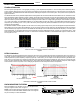
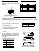
ENGLISH OVERVIEW Front Panel DFR22 FRONT PANEL Figure 1 1. INPUT/OUTPUT Level Meters: – CLIP. Illuminates at 3 dB below clipping level. – 0 VU. +4 dBu, –10 dBV; software selectable. 0 dB is equal to +4 dBu by default. If the input or output sensitivity is changed to –10 dBV using the DFR22 software, 0 dB equals –10 dBV. – –20 dB. Illuminates when the signal meets or exceeds the indicated level. – MUTE. Illuminates when input or output is muted. 5. BYPASS DFR FILTERS Button and LEDs.
ENGLISH DEFAULT PRESETS The DFR22 comes with three factory-configured presets. Although a computer is required to configure the DFR22’s equalizers, dynamics processors, delays, and crossover, you can use the DFR22 “out of the box” as an automatic feedback reducer, without connecting it to a computer. Preset 1: Provides two independent feedback reducers. The audio signal going to Input 1 is analyzed and filtered by a feedback reducer using up to 16 notch filters, and is then routed to Output 1.
ENGLISH DFR22 Theory Feedback Reduction No sound system (microphones + mixing/signal processing + power amplifiers/loudspeakers + room acoustics) has an absolutely flat frequency response. When the level of a sound system is increased, the frequencies at which peaks occur will be the first to exceed the feedback threshold. The DFR22 attenuates these frequencies, flattening the response of the sound system. The system can then operate at a higher overall level.
ENGLISH POWER AND INITIALIZATION Power Mains Connections Use the supplied power cable to connect the DFR22 Audio Processor to an active 100–240 Vac power source, as shown in Figure 6. The Power LED on the front panel will glow green when power is applied. NOTE: The DFR22 Audio Processor is designed to operate continuously. Therefore, there is no power on/off switch. ..
ENGLISH 12 dB and 18 dB Output Pads Each DFR22 output has a 12 dB pad and an 18 dB pad that can be engaged through the software interface. Use these pads when connecting the DFR22 to lower-level inputs. They cannot be used to prevent clipping at the output stage of the DFR22 NOTE: The Output meters indicate the signal level present at the digital-to-analog converters. The 12 and 18 dB pads act upon the signal after the digital-to-analog converters, so the meters do not reflect the pads.
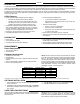
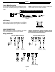
ENGLISH DIP Switch Settings for Networked Devices Assign each Shure Link device a unique Device ID Number, using DIP Switches 1–4, as shown in Figure 13. Refer to Table 2 for Device ID settings. IMPORTANT: Each Shure Link device MUST have a unique Device ID number. Table 2.
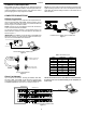
ENGLISH Mute Control Connections For mute control, use either a latching switch or a momentary switch. The total resistance of the cable run from the switch to the DFR22 should be less than 100 ohms. Figure 15 shows an example of how to connect either a latching switch or a momentary switch to the Control Input pins to mute an input or an output.
ENGLISH SPECIFICATIONS Frequency Response 20 Hz to 20 kHz ±1 dB Dynamic Range 110 dB minimum, A-weighted, 20 Hz to 20 kHz Sampling Rate 48 kHz Digital-to-Analog, Analog-to-Digital Conversion 24 bit Impedance Input: 10 kΩ Output: 120 Ω Input Clipping Level +24 dBu minimum Output Clipping Level +24 dBu +12 dBu (with 12 dB pad) +6 dBu (with 18 dB pad) Total Harmonic Distortion < 0.05%, +4 dBu, 20 Hz to 20 kHz Propagation Delay from Input to Output <1.
ENGLISH Information to User Changes or modifications not expressly approved by Shure Incorporated could void your authority to operate this equipment. This equipment has been tested and found to comply with the limits for a Class B digital device, pursuant to Part 15 of the FCC Rules. These limits are designed to provide reasonable protection against harmful interference in a residential installation.
SHURE Incorporated http://www.shure.com United States, Canada, Latin America, Caribbean: 5800 W. Touhy Avenue, Niles, IL 60714-4608, U.S.A. Phone: 847-600-2000 U.S.