IMPORTANT! DO NOT DESTROY Installation, Operation, & Maintenance Manual Shop Crane Customer Order No.
TABLE OF CONTENTS Parts List........................................................................................................................1-2 Introduction........................................................................................................................ 3 Installation Step 1 - Pre-assembly.....................................................................................................................3-4 Step 2 - Column Weldment Installation..............................
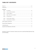
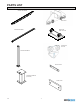
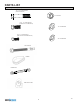
PARTS LIST See packing list for specific quantities.
PARTS LIST See packing list for specific quantities. 1/2-13, 3.5” LONG HEX BOLT (END STOP BOLTS) 1/2-13 HEX NUT 1/2-13, 1.
INTRODUCTION Thank you for choosing a Shop Crane by Gorbel®. The innovative design and solid construction of Shop Cranes will provide a superior quality product. Shop Crane is pre-engineered for powered hoist operation. The hoist weight allowance is 15% of the crane capacity (for example, a crane rated for 1000 pounds, allows for a 1000-pound live load plus 150 pounds for the weight of the hoist). There is also an allowance of 25% of the crane capacity for impact caused by hoist use.
STEP 1 - PRE-ASSEMBLY (CONTINUED) 1.3 Anchor bolts and concrete floor guidelines: • • HEX NUT Use 3/4”, grade 5 anchor bolts (included). LOCKWASHER Anchor bolts must be embedded at least 4” into floor, not to exceed 3/4 of floor depth (diagram 1A). FLATWASHER 3/4” Ø ANCHOR BOLT BASE ANGLE 1/2” Note: A minimum 6”-thick reinforced concrete floor is required. If other style anchor or floor conditions exist consult anchor manufacturer for requirements. 6” 4” MIN.
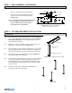
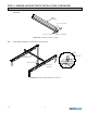
STEP 3 - RUNWAY INSTALLATION 3.1 Set the runways on top of the columns. Attach runways to columns using four (4) 1/2-13, 1.5” long bolts, hex nuts and lockwashers per column. 1/2-13, 1.5” LONG HEX BOLT RUNWAY WELDMENT 1/2” LOCKWASHER 1/2” HEX NUT COLUMN WELDMENT Diagram 3A. Attaching runway to column weldment. 3.2 Level runways and make sure that they are parallel within +/- 1/16”. Use shims under whole bracket if necessary. L+ RUNWAY /- 1 L+ /- 1 /16 ” ” COLUMN Diagram 3B.
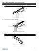
STEP 4 - BRIDGE AND END TRUCK INSTALLATION 4.1 Slide both end trucks into the runways (diagram 4A). TIP: Clean interior of tracks prior to end truck installation using dry vac or compressed air. RUNWAY END TRUCK Diagram 4A. Installing end truck on runway. 4.2 Install end stops into the runways (diagram 4B). END TRUCK 1/2” HEX NUT RUNWAY 1/2” LOCKWASHER 1/2-13, 3.5” LONG HEX BOLT Diagram 4B. Installing end stops on runway. 4.3 Slide hoist trolley into the bridge first.
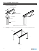
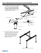
STEP 4 - BRIDGE AND END TRUCK INSTALLATION (CONTINUED) 4.4 Install end stops into both ends of the bridge using 1/2-13, 3.5” long hex bolts, 1/2” hex nut and the 1/2” lockwasher. BRIDGE WELDMENT 1/2-13, 3.5” HEX BOLT 1/2” HEX NUT 1/2” LOCKWASHER Diagram 4D. Installing end stops on bridge. 4.5 Place bridge weldment into U-bracket of each end truck. BRIDGE BRIDGE WELDMENT END TRUCK HOIST TROLLEY END TRUCK U-BRACKET Diagram 4E. Placing bridge weldment into end truck.
STEP 4 - BRIDGE AND END TRUCK INSTALLATION (CONTINUED) 4.6 Attach bridge weldment to the end trucks using clamp plate and spacer plate at one end. Make sure that the end truck at this end slides freely along the bridge. Center the bridge between end trucks and clamp opposite end truck to the bridge using the clamp plate without a spacer plate. Tighten two (2) 3/8-16, 1” long hex bolts until lockwasher is flattened.
STEP 5 - HOIST ATTACHMENT 5.1 Wire rope hoist attachment (diagram 5A) Attach wire rope hoist to hoist trolley using four 10mm hex bolts and 10mm lock washers included with wire rope hoist. Terminate power as required. 5.2 Standard hoist trolley attachment (diagram 5B) Attach hoist to hoist trolley by snapping hoist suspension hook over the trolley saddle clevis pin of hoist trolley. Diagram 5A. Wire rope hoist attachment. Diagram 5B. Standard hoist trolley. STEP 6 - RUNWAY TAGLINE INSTALLATION 6.
STEP 6 - RUNWAY TAGLINE INSTALLATION (CONTINUED) 6.2 Loop other end of cable around a thimble. Apply clamp as close to thimble as possible. Adjust cable as shown in diagram 6B. Tighten u-bolt to 10 ft.-lbs. of torque. WIRE ROPE CLAMP THIMBLE Diagram 6B. Attaching thimble to right end of cable. 168” Diagram 6C. 6.3 Attach tagline assembly using 1/2-13, 3” long hex bolt as shown in diagram 6D.
STEP 7 - COLUMN EXTENSION INSTALLATION 7.1 Place column extension weldment on top of column weldment. Make sure that slots in base plate are aligned. Use (4) 1/2-13, 2” long hex bolts, hex nuts and lockwashers per column. COLUMN EXTENSION WELDMENT 1/2-13, 2” LONG HEX BOLT 1/2” LOCKWASHER 1/2”-13 HEX NUT COLUMN WELDMENT Diagram 7A. Attaching column extension to column weldment. 7.2 Tighten hex nuts until lockwashers are flattened. Diagram 7B. Assembled column extension.
CRANE OPERATOR INSTRUCTIONS Overhead cranes generally handle materials over working areas where there are personnel. Therefore, it is important for the Crane Operator to be instructed in the use of the crane and to understand the severe consequences of careless operation. It is not intended that these suggestions take precedence over local codes. However, a thorough study of the following information should provide a better understanding of safe operation and afford a greater margin of safety.
LIMITED WARRANTY It is agreed that the equipment purchased hereunder is subject to the following LIMITED warranty and no other. The Company, warrants the manual push-pull Shop Crane by Gorbel products to be free from defects in material or workmanship for a period of two years or 1,000 hours use from date of shipment.
INSPECTION AND MAINTENANCE SCHEDULE ITEM 1 2 3 GORBEL® SHOP CRANE: INSPECTION AND MAINTENANCE SCHEDULE COMPONENT FREQUENCY* Runway/Column Hardware Check for full compression of lockwasher. Hoist Trolley / Wire Rope Trolley End Stops (both runway and bridge) 4 Wheels 5 End Trucks 6, 7 MAINTENANCE Every 1,000 hours Check clevis pin. Check cotter pin. (Cotter pin should be fully wrapped around clevis pin.) Check clevis bolt and hardware. Every 1,000 hours Check for full compression of lockwasher.