
Product Manual

STEP 1 - PRE-ASSEMBLY (CONTINUED)
1.3 Anchor bolts and concrete floor guidelines:
• Use 3/4”, grade 5 anchor bolts (included).
• Anchor bolts must be embedded at least 4”
into floor, not to exceed 3/4 of floor depth
(diagram 1A).
Note: A minimum 6”-thick reinforced concrete
floor is required. If other style anchor or
floor conditions exist consult anchor
manufacturer for requirements.
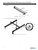
STEP 2 - COLUMN WELDMENT INSTALLATION
2.1 Lay out and mark on floor exact position of column weldments
prior to proceeding with installation (refer to enclosed General
Arrangement Drawing for recommended dimensions and
column weldment location).
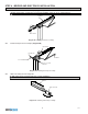
2.2 Position first column weldment in place. Orient column cap
plate (top of column) as shown in diagram 2A.
2.3 While supporting column weldment, drill holes in concrete floor
using pre-drilled holes in column weldment base angles as a
guide (use 3/4” drill bit). Vacuum or brush away cement dust.
2.4 Install anchor bolts and hardware according to diagram 1A.
Do not fully torque nuts at this point.
2.5 Check to see if column weldment is plumb. If column weldment
is not plumb, place steel shims (not included) or grout (not
included) under base of column weldment until plumb. After
column weldment is plumb, tighten all nuts to recommended
torque of 70 ft/lb.
2.6 Install remaining column weldments (repeat Steps 2.2
through 2.5). Add grout under base.
4
1/11
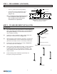
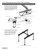
Diagram 1A. Anchor bolt embedment.
Max. anchor bolt load = 84 lbs.
IMPORTANT: Be sure that column cap plate (top of column) is oriented in the proper direction as shown in
diagram 2A.
Diagram 2A. Orienting column cap plate.
BASE ANGLE
1/2”
COLUMN CAP
PLATE
RUNWAY
COLUMN WELDMENT
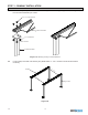
Diagram 2B.
3/4” Ø ANCHOR BOLT
HEX NUT
LOCKWASHER
FLATWASHER
4” MIN.
(EMBEDMENT)
6”