ADSL 2/2+ Ethernet Modem User Manual VERSION 1.
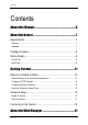
User Manual Contents About this Manual ...................................................................6 About the Router .......................................................................7 Requirements .....................................................................................7 Software .......................................................................................................................... 7 Hardware ......................................................................
User Manual Accessing the Web Manager............................................................21 Menus ...............................................................................................22 Basic Menu.................................................................................................................... 23 Advanced Menu............................................................................................................. 24 Help Menu .........................................
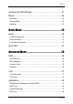
User Manual Port Forwarding............................................................................................................. 49 Bridge Filters ................................................................................................................. 52 Web Access Control...................................................................................................... 53 Quality of Service (QoS)...................................................................54 Egress .............
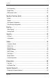
User Manual Changing the Timeout Settings ..................................................................................... 88 Firmware Upgrade............................................................................89 Save Settings....................................................................................90 Restart Router ..................................................................................90 Restore to Default..................................................................
User Manual About this Manual This manual provides a description of the components, basic operation, and advanced configuration options of the router. Scope This manual provides the installation instructions, router components, and configuration information through the Web manager. Target Audience This manual is designed for users who are required to install and maintain the router.
User Manual About the Router Congratulations on the purchase of your router. This router provides advanced features that allow you to converge your computer, Internet, and other network appliances into a single network through wired connection. Requirements Your computer must meet the following minimum requirements. Software Operating System: Any operating system can be used Browser: Internet Explorer 4.0 Netscape Navigator 3.
User Manual Package Contents Package contents are listed below. For any missing items, please contact your dealer immediately. Product contents vary for different models.
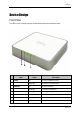
User Manual Device Design Front Panel The LEDs on the front panel gives you an idea about the power and connection status.
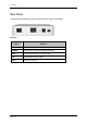
User Manual Back Panel The back panel provides ports to power up and connect the router into the network. Back Panel Label Used for… DSL Connecting the telephone cable ETHERNET Connecting with a computer/device through Ethernet cable RESET Resetting the device. Press for 10 seconds to reset.
User Manual Getting Started Setting up the device is easy. The flowchart below provides an outline of the steps you need to complete the installation. There are brief descriptions beside each step to help you along. Detailed instructions are provided in the subsequent pages.
User Manual Remove or Disable Conflicts To make sure the router installation moves on smoothly, you need to remove or disable conflicts that may interfere the installation. Probable conflicts may include: Internet sharing applications Proxy software Security software TCP/IP settings Internet properties Temporary Internet files Internet Sharing, Proxy, and Security Applications Internet sharing, proxy software, and firewall applications may interfere with the router installation.
User Manual Configuring TCP/IP Settings Use the default TCP/IP settings to allow the router to provide a network address to the computer, To set the TCP/IP properties: 1. Select Start > Run. This opens the Run dialog box. 2. Enter control ncpa.cpl and then click OK. This opens the Network Connections in your computer. 3. Right-click LAN and then select Properties. This opens the Local Area Connection Properties dialog box. 4. Select Internet Protocol (TCP/IP) and then click Properties.
User Manual To remove temporary Internet files: 1. Select Start > Run. This opens the Run dialog box. 2. Enter control and then click OK. This opens the Control Panel. 3. Double-click Internet Options. This opens the Internet Options dialog box. 4. In the Temporary Internet Files pane, click Delete Cookies. 5. Click Delete Files. 6. Click OK to close the Internet Properties dialog box.
User Manual Hardware Setup When installing the router, the common practice is to have the router, the main computer, and phone jack in the same room. The room should also have enough electrical outlets to match your needs. The following hardware setup samples depict two scenarios – Bridge Connection and Direct Connection. Bridge Connection This device is preconfigured to function as a bridge connector between the Internet service and the local network.
User Manual POTS Splitter A phone line can carry phone call and Internet signals. When you enable the phone line for high speed Internet, the connection produces high-pitched tones when using the phone. Installing a Plain Old Telephone Service (POTS) splitter separates the two signals and eliminates the noise. To setup the telephone POTS Splitter: 1. Locate the phone jack in your house. 2. Insert the POTS Splitter into the phone jack. 3.
User Manual Direct Connection When a computer is directly connected to the modem, you can use it to connect to the Internet. To setup a direct connection: 1. Plug one end of the telephone cable from the POTS Splitter’s ADSL port and then plug the other end into the router’s DSL port POTS Splitter A phone line can carry phone call and Internet signals. When you enable the phone line for high speed Internet, the connection produces high-pitched tones when using the phone.
User Manual 2. Plug one end of the Ethernet cable from the router’s ETHERNET port and then plug the other end into the Ethernet port in your computer. 3. Connect the power adapter from the router’s 9V DC port into the electrical outlet and then press ON.
User Manual Connecting to the Internet Use the Web Manager’s Quick Start to connect to the Internet. Note: These connection settings only apply if your computer is directly connected to the router. To connect to the Internet: 1. Open your browser. 2. Enter 192.168.1.1 in the address field and then press Enter. This opens the Log In page of Web Manager. 3. Enter the Username and Password for the Web Manager. The default Username and Password is admin. Log In 4. Click Log In. 5.
User Manual 7. Click Connect. When the connection attempt is successful, the Basic Home page appears. When the connection attempt is not successful, a message will ask you to verify the Username and Password.
User Manual About the Web Manager The Web Manager is used to configure the router settings. Accessing the Web Manager To access the Web Manager: 1. Open a browser. 2. Enter the router’s IP Address. The default IP Address is 192.168.1.1. 3. When authentication is enabled, the log in page will appear. In the login page, enter the Username and Password. The default Username and Password is admin. 4. Click Login.
User Manual Menus The web interface includes the following menus: Basic Menu Advanced Menu Help Menu Page 22 of 92
User Manual Basic Menu The Basic Menu includes the Home and Quick Start links.
User Manual Advanced Menu The Advanced Menu provides advanced configuration settings for existing connections. At least one WAN connection must be configured before implementing advanced WAN configuration features. At least one LAN group must be defined before implementing advanced LAN configuration features.
User Manual Help Menu The Help Menu provides documentation about various router features.
User Manual Basic Menu The options for the Basic Menu include: Home Quick Start Home The Home page provides a one-page summary about the Connection Information, Router Information, and Local Network settings. Basic Home Connection Information The Connection Information pane gives you an idea about the status of your Internet connection. This pane includes a Connect/Disconnect button. When clicked, the router makes an attempt to connect to the Internet using the parameters saved in the router.
User Manual Router Information This pane provides all the necessary information to determine the model, firmware version, build, Ethernet MAC Address, NAT status, and Firewall status. Local Network Information The Local Network pane displays the current IP address of the router. It also provides the DHCP status, DHCP Range, and Ethernet status. Quick Start Quick Start gives you the ability to instantly connect to the Internet.
User Manual Advanced Menu The Advanced Menu provides advanced configuration options.
User Manual WAN Wide Area Network refers to the configurations you perform to establish an Internet connection. There are several types of WAN connections that require different settings. New Connection Your router supports the creation of new connections. If you have multiple virtual connections, you may need to utilize the static routing capabilities of the modem to pass data correctly.
User Manual PPPoE Connection PPPoE is a common WAN connection type used to connect to the Internet. PPP, or point-to-point protocol, is a method of establishing a network connection/session between network hosts. PPPoE is a protocol for encapsulating PPP frames in Ethernet frames and is described in RFC 2516. PPPoE provides the ability to connect to a network of hosts over a simple bridging access device to a remote access concentrator. With this model, each router uses its own PPP stack.
User Manual PPPoA Connection Another commonly used WAN connection type is PPPoA. PPPoA is also known as RFC 2364. It is a method of encapsulating PPP packets in ATM cells that are carried over the DSL line. PPP, or point-topoint protocol, is a method of establishing a network connection/session between network hosts. It usually provides a mechanism of authenticating users. Logical Link Control (LLC) and Virtual Circuit (VC) are two different methods of encapsulating the PPP packet.
User Manual Static Connection Static connection type is used whenever a known static IP address is assigned to the router. Additional addressing information such as the Subnet Mask and the Default Gateway must also be specified. Up to three Domain Name Server (DNS) addresses can be identified. These servers resolve the name of the computer to the IP address mapped to it and thus enable you to access other web servers by typing the symbolic name (host name).
User Manual DHCP Connection DHCP allows the router to automatically obtain the IP address from the server. This option is commonly used when the IP is dynamically assigned and is not known prior to assignment.
User Manual Bridge Connection A bridge connection does not assign any IP address to the WAN interface. NAT and firewall rules are not enabled. This connection method makes the router act as a bridge for passing packets between the WAN interface and the LAN interface.
User Manual ADSL Modulation ADSL Modulation allows you to select any combination of DSL training modes. Leave the default value if you are unsure or the service provider did not provide this information. In most cases, this screen should not be modified. ADSL Modulation Connection Scan This feature helps users to detect the PVC settings provided by the service provider. Before the router can begin scanning the connection, the telephone line has to be plugged into the router.
User Manual Quickstart Click to open the Quickstart Setup page. Quickstart is the connection name of the default PPPoE WAN Connection. In this page, you can change the connection details.
User Manual LAN The router is preconfigured to automatically provide an IP address to each Ethernet device connected in the local area network (LAN). However, if you are familiar with your network setup, you can manually configure the LAN settings. LAN Configuration Your router’s default IP address and subnet mask are 192.168.1.1 and 255.255.255.0, respectively. This subnet mask allows the router to support 254 users.
User Manual To configure the LAN groupings: 1. From the Advanced Menu, select LAN > LAN Configuration. 2. Select ETHERNET in LAN group 1 and then click < Remove. No packets will be sent to the ETHERNET interface because it does not belong to any LAN group. 3. Select ETHERNET from Interfaces and then click Add > under LAN group 2. Just like in LAN group 1, Configure will appear in LAN group 2 to allow the definition of additional configurations. 4. To temporarily activate the settings, click Submit. 5.
User Manual LAN Group Configuration LAN Group Configuration allows you to configure settings for each LAN group. Notice that you can also view the status of advanced services that can be applied to a LAN group. Green indicates that the service is enabled, while red indicates that the service is disabled. LAN Group Configuration Category Field Description Unmanaged Unmanaged is a state when the LAN group is not configured and no IP address has been assigned to the bridge.
User Manual subnet allows the router to support 254 users. If you want to support a larger number of users you can change the subnet mask. Default Gateway The default gateway is the routing device used to forward all traffic that is not addressed to a station within the local subnet. Your ISP provides you with the IP address of the default gateway. Host Name The host name is used in conjunction with the domain name to uniquely identify the router.
User Manual DHCP relay function. When the router is configured as DHCP server, it assigns the IP addresses to the LAN clients. When the gateway is configured as DHCP relay, it is responsible for forwarding the requests and responses negotiated between the DHCP clients and the server. Relay IP Server and Relay Off The IP address of the DHCP relay server.
User Manual LAN Clients LAN Clients allows you to view and add computers in a LAN group. Each computer either has a dynamic or static (manually-configured) IP address. You can add a static IP address (belonging to the router’s LAN subnet) using the LAN Clients page. Any existing static entry falling within the DHCP server's range can be deleted. LAN Clients To add LAN Clients: 1. From the Advanced Menu, select LAN > LAN Clients. This opens the LAN Clients page. 2.
User Manual Applications Applications include: Simple Network Management Protocol Internet Group Management Protocol (IGMP) Proxy TR-068 WAN Access DNS Proxy Port Forwarding Bridge Filters Web Access Control Page 43 of 92
User Manual Simple Network Management Protocol (SNMP) SNMP (Simple Network Management Protocol) is a troubleshooting and management protocol, which uses the UDP protocol on port 161 to communicate between clients and servers. SNMP uses a manager MIB (management information base) agent solution to fulfill the network management needs. The agent is a separate station that can request data from an SNMP agent in each of the different system in the network.
User Manual IGMP Proxy IP hosts use Internet group management protocol (IGMP) to report their multicast group memberships to neighboring routers. Similarly, multicast routers use IGMP to discover which of their hosts belong to multicast groups. Your router supports IGMP proxy that handles IGMP messages. When enabled, your router acts as a proxy for a LAN host making requests to join and leave multicast groups, or a multicast router sending multicast packets to multicast groups on the WAN side.
User Manual The IGMP Proxy page allows you to enable multicast on available WAN and LAN connections. You can configure the WAN or LAN interface as one of the following: Upstream The interface that IGMP requests from hosts are sent to the multicast router. Downstream The interface data from the multicast router are sent to hosts in the multicast group database. Ignore No IGMP request nor data multicast are forwarded. You can perform one of the two options: 1.
User Manual TR-068 WAN Access (Optional) The TR-068 WAN Access page enables you to give temporary permission to someone (such as technical support staff) to be able to access your router from the WAN side. From the moment the account is enabled the user is expected to log in within 20 minutes, otherwise the account expires. Once the user has logged in, if the session remains inactive for more than 20 minutes, the user will be logged out and the account expires.
User Manual DNS Proxy DNS Proxy determines the primary Domain Name Server and secondary DNS to be used. DNS Proxy To select the DNS Server Priority: 1. From the Advanced Menu, Select Application > DNS Proxy. 2. Select the DNS Server Priority: Only Auto Discovered DNS Servers Only User Configured DNS Servers Auto Discovered then User Configured User Configured then Auto Discovered 3. Click Submit to temporarily apply settings. 4. To make changes permanent, click Save Settings.
User Manual Port Forwarding Port forwarding (or virtual server) allows you to direct incoming traffic to specific LAN hosts based on a protocol port number and protocol. Using the Port Forwarding page, you can provide local services (for example, web hosting) for people on the Internet or play Internet games. Port forwarding is configurable per LAN group. Port Forwarding A database of predefined port forwarding rules allows you to apply one or more rules to one or more members of a defined LAN group.
User Manual If a rule is not in the list, you can create your own rule in the User category. To create a new rule, select User as the Category, and then click New. The Rule Management page opens. Enter Rule Name, Protocol, Port Start, Port End, and Port Map, and then click Submit. 6. Click Submit to temporarily activate the settings. 7. To make changes permanent, click Save Settings.
User Manual To enable DMZ Settings: 1. From the Advanced Menu, select Application > Port Forwarding. 2. Select DMZ. This opens the DMZ Settings page. 3. Select Enable DMZ. 4. Select the WAN Connection. 5. Select a LAN Group. 6. Select a LAN IP Address. 7. Click Submit to temporarily apply the settings. 8. To make changes permanent, click Save Settings.
User Manual Bridge Filters The Bridge Filters allows you to enable, add, edit, or delete the filter rules. When bridge filtering is enabled, each frame is examined against every defined filter rule in sequence. When a match is found, the appropriate filtering action (allow or deny) is performed. Up to 20 filter rules are supported with bridge filtering. Bridge Filters To configure Bridge Filters: 1. From the Advanced Menu, select Application > Bridge Filters. This opens the Bridge Filters page. 2.
User Manual Web Access Control The Web Access Control page allows you to access the router via the web from a remote location like your home or office. Web Access Control To configure Web Access: 1. From the Advanced Menu, select Application > Web Access Control. 2. Select Enable Web Access Control. 3. Select the Connection. 4. Configure the following fields: Remote Host IP Remote Netmask Redirect Port 5. Click Submit to temporarily activate the settings on the page.
User Manual Quality of Service (QoS) Quality of service allows network administrators to configure the routers to meet the real time requirements for voice and video. Different networks use different QoS markings like: ToS network: ToS bits in the IP header VLAN network: priority bits in the VLAN header DSCP network: uses only 5 bits of the CoS WLAN: WLAN QoS header. The QoS framework is supported on all the above domains.
User Manual The rules are: 1. CoS1 has absolute priority and is used for expedited forwarding (EF) traffic. This is always serviced till completion. 2. CoS2-CoS5 is used for assured forwarding (AF) classes. They are serviced in a strict round robin manner using the following priority scheme: CoS2 > CoS3 > CoS4 > CoS5 3. CoS6 is for best effort (BE) traffic. This is only serviced when there is no other class of service. If QoS is not enabled on your router, all traffic will be treated as best effort.
User Manual Egress For packets going out of the router, the markings (CoS) need to be translated to the mappings understood by the network domains. The reverse CoS and domain mapping is configured using the Egress. To access Egress, select QoS > Egress from the Advanced Menu. There are three Egress modes: No Egress mode Layer 2 Layer 3 No Egress Mode The default Egress page setting for all interfaces is No Egress. In this mode, the domain mapping of the packets are untouched.
User Manual Layer 2 The Egress Layer 2 page allows you to map the CoS of an outgoing packet to user priority bits, which is honored by the VLAN network. Again, this feature is only configurable on the WAN interfaces as VLAN is only supported on the WAN side in the current release. Layer 2 Field Description Interface Select the WAN interface to configure the QoS for outgoing packets; LAN interface cannot be selected as VLAN is currently supported on the WAN side only.
User Manual Layer 3 Egress Layer 3 enables you to map CoS to ToS so that the priority marking of outgoing packets can be carried over to the IP network. Layer 3 Field Description Interface Select the WAN interface to configure the QoS for outgoing packets; LAN interface cannot be selected as VLAN is currently supported on the WAN side only. Default Non-IP Locally generated packets (such as ARP packets) do not have a CoS marking.
User Manual Ingress Ingress enables you to configure QoS for packets as soon as they come into the router. The domain mappings are converted to CoS (the common language) so that the priority marking is carried over. There are four Ingress modes: Untrusted mode Layer 2 Layer 3 Static Untrusted Mode Untrusted is the default Ingress page setting for all interfaces. In this mode, no domain mapping is honored in the router. All packets are treated as CoS6 (best effort).
User Manual Layer 2 Layer 2 allows you to map an incoming packet with VLAN priority to CoS. This feature is only configurable on the WAN interfaces as VLAN is only supported on the WAN side in the current software release. Layer 2 Field Description Interface Select the WAN interface here to configure the CoS for incoming traffic. Only WAN interface can be selected as VLAN is currently supported only on the WAN side.
User Manual Layer 3 The Layer 3 page allows you to map ToS bits of incoming packets from the IP network to CoS for each WAN/LAN interface. Layer 3 Field Description Interface For both WAN and LAN interfaces, you can configure QoS for layer 3 (IP) data traffic. Class of Service This CoS field allows you to map incoming layer 3 WAN/LAN packets to one of the following CoS (in the order of descending priority): CoS1, CoS2, CoS3, CoS4, CoS5, and CoS6.
User Manual Static The Ingress - Static page enables you to configure a static CoS for all packets received on a WAN or LAN interface. Static To access Ingress Layer 3: From the Advanced Menu, select QoS > Ingress.
User Manual QoS Shaper Configuration The Shaper Configuration page is accessed by selecting Shaper on the Advanced main page. Three shaper algorithms are supported: HTB Low Latency Queue Discipline PRIOWRR QoS Shaper Configuration Note: Egress TCA is required if shaper is configured for that interface. Field Description Interface The selections are WAN/LAN interfaces except WLAN, which does not support Shaper feature. This field needs to be selected before shaper configuration.
User Manual PRIOWRR This is a priority based weighted round robin algorithm operating on CoS2-CoS6. CoS1 queues have the highest priority and are not controlled by the WRR algorithm. Of the three shaping algorithms available on the Shaper Configuration page, only one can be enabled at a time. An example of each configuration is given as follows. Example 1: HTB Queue Discipline Enabled In the example below, HTB Queue Discipline is enabled.
User Manual Example 2: Low Latency Queue Discipline Enabled In this second example, Low Latency Queue Discipline is enabled. CoS1 is not rate controlled (hence the field is disabled). CoS2 takes 100 Kbps when there are no CoS1 packets. CoS6 has 300 Kbps when there is no CoS1 or CoS2 packets. This is similar to the HTB queue discipline as they are both rate-based algorithm, except that CoS1 is handled differently.
User Manual Example 3: PRIOWRR Enabled In this third example, PRIOWRR is enabled. Since PRIOWRR operates only on the number of packets being transmitted, the max rate field has been disabled. Only percentage can be assigned to the CoS2 - CoS6. CoS1 is not rate controlled (hence the field is not displayed). When there are no CoS1 packets, CoS2, CoS3, CoS4 each has 10 percent, and CoS6 has 70 percent.
User Manual Policy Routing Configuration The Policy Routing Configuration enables you to configure policy routing and QoS. Policy Routing Configuration Field Description Ingress Inter face The incoming traffic interface for a Policy Routing rule. Selections include LAN interfaces, WAN interfaces, Locally generated (traffic), and not applicable. Examples of Locally generated traffic are: voice packets, packets generated by applications such as DNS, DHCP, etc.
User Manual protocol first. Source MAC The MAC address of the traffic source. Local Routing MAC This field is enabled only when Locally Generated is selected in the Ingress Interface field.
User Manual The following fields can be configured for Policy Routing: Destination IP address/mask Source IP address/mask Source MAC address Protocol (TCP, UDP, ICMP, etc) Source port Destination port Incoming interface DSCP Page 69 of 92
User Manual Routing Routing options include: Static Routing Routing Table Static Routing If the router is connected to more than one network, you may need to set up a static route between them. A static route is a pre-defined pathway that network information must travel to reach a specific host or network. You can use static routing to allow different IP domain users to access the Internet through the router.
User Manual Routing Table Routing Table displays the information used by routers when making packet-forwarding decisions. Packets are routed according to the packet's destination IP address.
User Manual Security Security options include: IP Filters LAN Isolation IP Filters IP filtering allows you to block specific applications/services based on the IP address of the LAN device. In this page, you can block specific traffic (for example, block web access) or any traffic from a host on your local network. A database of predefined IP filters allows you to apply one or more filtering rules to one or more members of a defined LAN group.
User Manual To configure IP Filters: 1. From the Advanced Menu, select Security > IP Filters. 2. Select a LAN Group. 3. Select a LAN IP. If the desired LAN IP is not available in the LAN IP drop-down menu, click New IP to add an IP. 4. Select Available Rules and then move them into Applied Rules. To select a rule, select a Category then select an available rule based on the selected Category. Click View to view the rule settings. If a rule is not in the list, you can create your own rule.
User Manual LAN Isolation LAN isolation allows you to disable the flow of packets between two LAN groups. This allows you to secure information in private portions of the LAN from other publicly accessible LAN segments. LAN Isolation To enable LAN Isolation: 1. From the Advanced Menu, select Security > LAN Isolation. 2. Check an option. 3. To temporarily implement the changes, click Submit. 4. To make changes permanent, click Save Settings.
User Manual Status This chapter provides information about monitoring the router status and viewing product information.
User Manual Connection Status Connection Status displays the type of protocol, the WAN IP address, the connection state and the duration of your Internet connection. To view the Connection Status from the Advanced Menu, select Status > Connection Status.
User Manual System Log System Log displays the router log. Depending on the severity level, the information log will generate log reports to a remote host if remote logging is enabled. To view the System Log from the Advanced Menu, select Status > System Log.
User Manual Remote Log Remote Log allows you to forward all logged information to one (or more) remote computer. The type of information forwarded to the remote computer depends on the Log level. Each log message belongs to a certain log level, which indicates the severity of the event. When you configure remote logging, you must specify a severity level.
User Manual Info Events or non-error conditions of interest. Debug Software debugging message. Specify this level only when directed by a technical support representative. 3. Enter the IP Address where the log will be sent to. 4. Click Add. 5. Click Submit. The IP address will appear in the Select a logging destination drop- down menu. 6. To make changes permanent, click Save Settings.
User Manual Network Statistics The Ethernet and DSL line statuses are displayed in this page. To view the Network Statistics from the Advanced Menu, select Status > Network Statistics. There are three categories for Network Statistics. These include Ethernet and DSL.
User Manual DHCP Clients DHCP Clients displays the MAC address, IP address, host name, and lease time. To view the DHCP Clients from the Advanced Menu, select Status > DHCP Clients. The DHCP Clients are displayed according to LAN Group.
User Manual QoS Status This page displays the Quality of Service and the packet statistics. To view the QoS Status from the Advanced Menu, select Status > QoS Status.
User Manual Modem Status This page displays the model status. To view the Modem Status from the Advanced Menu, select Status > Modem Status.
User Manual Product Information This page displays the product information and software versions. To view the Product Information from the Advanced Menu, select Status > Product Information.
User Manual Diagnostics Diagnostic Test is used for investigating whether the router is properly connected to the WAN Network. This test may take a few seconds to complete. To perform the test, select your connection from the list and click Test. Before running this test, make sure you have a valid DSL link. Diagnostics To run diagnostic test: 1. From the Advanced Menu, select Diagnostics. This opens the Diagnostics page. 2. Click Test. The test status will appear after running the diagnostic test.
User Manual 4. Click Test. The ping results are displayed in the page. If the ping test was successful, it means that the TCP/IP protocol is up and running. If the Ping test failed, you should restart the router. Full Modem Test This test is used to check if your modem is properly connected to the network. To perform a Full Modem test: 1. From the Advanced Menu, select Diagnostics. This opens the Diagnostics page. 2. Click Full Modem Test. This opens the Modem Test page. 3.
User Manual System Password Anyone who can access the web interface can be considered an Administrator. To restrict access to the web interface, you need to set the System Password. System Password Changing the System Password To change the System Password: 1. From the Advanced Menu, select System Password. This opens the System Password page. 2. Check Enable Authentication. 3. Enter your password. 4. Reenter your password in the Confirm Password text box. 5.
User Manual Changing the Timeout Settings To change the timeout settings: 1. From the Advanced Menu, select System Password. 2. Select Enable Authentication. 3. Enter the number of minutes in the Idle Timeout text field. 4. To temporarily implement the settings, click Submit. 5. To make changes permanent, click Save Settings.
User Manual Firmware Upgrade When updating the firmware, make sure you are using the correct file. Once the upgrade is complete the router will reboot. You will need to log back into the router after the firmware upgrade is completed. Firmware upgrade To update the firmware: 1. From the Advanced Menu, select Firmware Upgrade. This opens the Firmware Upgrade page. 2. Click Browse and then locate the firmware file. 3. Click Update Gateway. The update may take a few minutes.
User Manual Save Settings Select to apply configuration changes permanently. Restart Router Select to restart the router. Restore to Default Select to reset the router to its factory default settings.
User Manual Help Menu To access Help, select the Help Menu.
User Manual Safety Precautions Do not open, service, or change any component. Only qualified technical specialists are allowed to service the equipment. Observe safety precautions to avoid electric shock. Check voltage before connecting to the power supply. Connecting to the wrong voltage will damage the equipment. Reminder: Product warranty does not apply to damage caused by lightning, power surges, or wrong voltage usage. Copyright © 2007. All rights reserved.