
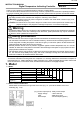
User Manual

4
4. Wiring
Warning
Turn the power supply to the instrument off before wiring or checking. Working on or touching the
terminal with the power switched on may result in severe injury or death due to Electric Shock.
Caution
• The terminal block of this instrument is designed to be wired from the left side.
The lead wire must be inserted from the left side of the terminal, and fastened with the terminal screw.
The torque should be 0.63N•m.
• To extend a thermocouple’s lead wire, be sure to use a compensating lead wire in accordance with
the sensor input specification.
(If any other compensating lead wire is used, a temperature indication error may be caused.)
• Use the 3-wire RTD in accordance with the sensor input specifications of this controller.
• This instrument does not have a built-in power switch, circuit breaker or fuse. It is necessary to install
them near the controller.
(Recommended fuse: Time-lag fuse, rated voltage 250V AC, rated current 2A)
• When using a relay contact output type, externally use a relay in accordance with the capacity of the
load.
• When wiring, keep input wires (thermocouple, RTD, etc.) away from AC sources or load wires.
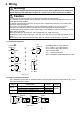
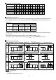
4.1 Terminal arrangement
• POWER SUPPLY: 100 to 240V AC
• EV1 : Event 1 (A1) output (option)
• EV2 : Event 2 (A2) output (option)
• OUT: Control output
• TC : Thermocouple input
• RTD : Resistance temperature detector input
(Fig. 4.1-1)
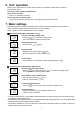
4.2 Lead wire solderless terminal
Use a solderless terminal with an insulation sleeve in which an M3 screw fits as shown below. (Fig. 4.2-1)
The torque should be 0.63N•m.
Solderless
terminal
Manufacturer Model Torque
Nichifu Terminal Industries CO.,LTD. TMEV1.25Y-3
Y type
JapanSolderless Terminal MFG CO.,LTD. VD1.25-B3A
Nichifu Terminal Industries CO.,LTD. TMEV1.25-3
Ring type
JapanSolderless Terminal MFG CO.,LTD. V1.25-3
0.63N•m
(Fig. 4.2-1)
5.8mm or less
5.8mm or less
3.2mm
3.
2mm
①
②
③
④
⑤
⑥
⑬
⑭
⑮
⑯
⑰
⑱
⑦
⑧
⑨
⑩
⑪
⑫
POWER
SUPPLY
100 to 240V AC
EV1
EV2
NO
NO
NO
OUT
+
-
A
B
B
RTDTC
-
+
3A
250V AC
!
3A
250V AC
3A
250V AC