SC600 User’s Manual WinCE. NET Rugged Portable Data Terminal Jan/23/2006 Ver: 0.
Table of Contents Chapter 1. Introduction ...................................................................... 1-1 1.1 About this Manual............................................................................1-1 1.2 User and Product Safety ..................................................................1-1 1.3 Radio Frequency Interference Information......................................1-3 1.3.1 FCC Radiation Exposure Statement .......................................1-3 1.4 Product Labeling.......
2.6 Power management........................................................................2-27 2.6.1 Suspend Mode.......................................................................2-27 2.6.2 Resuming ..............................................................................2-28 2.7 Resetting the PDT..........................................................................2-28 2.7.1 Software (Warm) Reset.........................................................2-28 2.7.2 Cold Reset..................
.2.2 ActiveSync File Synchronization............................................4-3 4.3 Networking ......................................................................................4-3 Chapter 5. Software Applications....................................................... 5-1 5.1 Introduction......................................................................................5-1 5.2 Software Applications......................................................................5-1 5.2.1 Inbox............
Chapter 1. Introduction Congratulations on purchasing the SC600 Portable Data Terminal (PDT), a Microsoft Windows® CE .Net rugged PDT. Its special combination of features makes it perfect for using in a wide range of applications. These features as: λ λ λ λ λ λ λ λ λ Intel® XScaleTM PXA255 400MHz 32 bits RISC Processor Windows® CE .NET 4.2 Operating System 64/128/256 MB SDRAM & 64/128 MB Flash ROM Open Architecture: User Accessible SD/CF/PCMCIA Slot 240 x 320, 3.
contaminants entering into the PDT. ◆ Use only the approved AC Adapter with the PDT. Use of an unapproved AC Adapter could result in electrical problems, or even cause a fire or electrical shock to the user. ◆ Be sure that only authorized supplier are allowed to disassemble and reassemble the device. If the device or parts has been damaged due to any wrong handling, shall void the product and parts warranty. ◆ Always make back-up copies of all important data.
1.3 Radio Frequency Interference Information 1.3.1 FCC Radiation Exposure Statement This equipment has been tested and found to comply with the limits for a Class B digital device, pursuant to Part 15 of the FCC Rules. These limits are designed to provide reasonable protection against harmful interference in a residential installation.
IMPORTANT NOTE: FCC Radiation Exposure Statement: This equipment complies with FCC RF radiation exposure limits set forth for an uncontrolled environment. To maintain compliance with FCC RF exposure compliance requirements, please avoid direct contact to the transmitting antenna during transmitting. This transmitter must not be co-located or operating in conjunction with any other antenna or transmitter. Caution: Please also note that SC600 is limited in CH1~CH11 for 2.
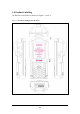
1.4 Product Labeling The PDT has several labels as showed in Figure 1-1 and 1-2.
Figure 1-2 Product Labeling (Back side view) 1.5 System Specifications The SC600 PDT detailed specifications as follows. Unless otherwise noted, all the specifications are subject to change without prior notification. Table 1-1 System Specification SC600 Processor - 400MHz Intel PXA255 32 bits RISC CPU Memory - 64 or 128MB Flash ROM - 64,128 or 256MB SDRAM Display - 240 x 320 3.5” TFT 256K Color LCD with LED backlight Audio - One mono speaker - 2.
SC600 Radio Support Communication Ports Scan Engine Expansion Slot - Wireless LAN: 802.11b - Bluetooth: Class II (optional) - GSM/GPRS: (optional) - USB: Support USB v1.1 both host and client. (PDT and Cradle) - Serial: RS232 via optional cable or Cradle. - Default: Opticon Laser (1D) Engine - Optional: HHP 2D Imager.
SC600 Peripherals and Accessories Software - Optional: RS232 Serial Cable for Terminal / USB Host Cable for Terminal / High-Capacity Li-Ion Battery Pack (3.7VDC, 4000 mAh) / RFID Card Cover / Single Dock / Pistol Grip/ 4 Slot Battery Charger / Car Adapter / Holster / Protect Film - Microsoft Windows CE.NET 4.2 Professional 1.
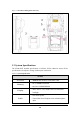
Chapter 2. Getting Started 2.1 Check the package Open the package and check all the parts are inside without shortage and damage: Figure 2-1 Inside the package 1. SC600 Terminal 2. Stylus 3. USB Client Cable for Terminal 4. Earphone/ Microphone Set 5. Standard AC Adapter 5VDC/2.6A 6. AC Power Cord 7. Standard Battery Pack (3.7VDC, 3000 mAh) 8. CF Card Support Guide 9.
2.2 General View of the PDT 2.2.
2.2.
Table 2-1 Description of PDT General View 1 Scanner LED Indicator “Red” color Reading barcode “Green” color Successful reading Charge LED Indicator “Red” color Charging battery 3 LCM / Touch Panel “Green” color Battery charged full Do specific action through touch panel by stylus 4 Left Scan key Right Scan key Scan key Start scanning the barcode by pressing any one of these three scan keys 5 Power key Puts the terminal into and wakes the terminal from suspend mode.
2.3 Charging the Battery Pack Before using the PDT, perform the basic procedure of charging the battery pack through the following steps. 2.3.1 Installing the battery pack 1. On the PDT attached with a hand-strap, detach and loose the hand-strap. Figure 2-4 Release the Hand strap from PDT 2. Turn the locking screws (right and left) downwards and lift the battery cover away from the PDT.
3. Insert the battery pack into the battery compartment with the label facing out, and ensuring the battery snaps into place. Figure 2-6 Insert the battery pack 4. Replace the battery cover by inserting the top first, and then press the bottom in firmly. Turn the locking screws (right and left) upwards to secure the cover to the PDT.
5. Charge time. For the first time to charge the battery pack needs approximately 6 hours. Subsequent charging time needs approximately 4 hours. ◆. When charging the battery pack, the charge LED indicator on the PDT turns on Red. After the battery pack is fully charged, the charge LED indicator turns to Green. 2.3.2 Charging the battery pack with Power Adapter 1. Connect the Power cord to the Power adapter. 2. Plug in the connector of the power adapter. 3. Connect the power cord to a power source.
2.3.3 Charging the battery pack with Single Dock a) 1. 2. 3. 4. Leave the battery pack inside of the PDT Connect the Power cord to the Power adapter Connect the power cord to a power source Plug in the connector of the power adapter with Single Dock Insert the PDT into the Single Dock Figure 2-9 Charging with Single Dock ◆ When charging the battery pack, the charge LED indicator on the PDT turns on Red. After the battery pack is fully charged, the charge LED indicator turns to Green.
◆ When charging the Battery pack in the Single Cradle’s spare Battery slot, the Single Cradle charging LED will turn on Red. After the Battery pack is fully charged, this LED will turn to Green. CAUTION: Please do not remove the Battery pack too long from PDT after you have already full-charged the Battery pack and backup battery pack and start to use the PDT. Otherwise the data stored inside SDRAM memory will be lost. Please also keep in mind power the PDT off if you want to change the main Battery pack.
2.4. Handling the PDT 2.4.1 Starting the PDT Press the Power key to turn on/off the PDT. If the PDT does not power on, perform a cold boot. See 2-7 Resetting on page 2-27. CAUTION: When a battery is fully inserted in PDT for the first time, upon the PDT’s first power up, the device boots and powers on automatically. When the PDT is powered on for the first time, it initializes its system. A splash screen (figure 2-10) appears for a short period of time followed by the Wince.NET 4.2 window.
2.4.3 Calibration of the touch Screen On the initial boot-up of the PDT, the stylus calibration screen (Labeled Align Screen) opens. Use the stylus to press and hold briefly on the center of each target as it moves around the screen. If necessary, adjust the backlight on the PDT to make the screen readable. (See below 2.4.4. Adjust the brightness).
2.4.5 To mute the Sound To mute the sound, press the off and on of the sound. key first, and then press the key to turn 2.4.6 Using the Stylus The stylus is located next to hand-strap on the left rear of the PDT as illustrated in figure 2-3 PDT Back side view (in page 2-3). The stylus function is same as the mouse on a PC. Use the stylus to: 1) Navigate the display, select menu item and open optional applications. 2) Tap the characters on soft keyboard panel.
Table 2-2 Keypad List Key Main Function Fn + Main Function Alpha + Main Function None.
Key Main Function Fn + Main Function 0 Space . (Point) Start Menu (Backslash) Enter Alpha + Main Function 〔 〕 , ; = % Table 2-3 Special Assembler Key Assembler Key Functionality Definition Warm Reset Press “F1” and “F4” button simultaneously. Cold Reset Press “F1”, “F4” and “Power” button simultaneously. Table 2-4 Definition of main Function Key Main Function None. Definition Keep its function or by customer demand. Main BarCode Scan The key activates the scan Key function of SC600.
Key Main Function Definition Down Move the cursor down one row or line The cursor will move continuously if button is pressed continuously. Up Move the cursor up one row or line The cursor will move continuously if button is pressed continuously. ESC This key performs a cancel action Backspace “Backspace” key, it moves the cursor back one space each time the key is pressed. It deletes the previous character each time it is pressed if you are typing text.
Key Main Function Definition 7 Number key “7” 8 Number key “8” 9 Number key “9” 0 Number key “0” . Point key Enter This key confirms data entry 2.4.7.1 Special Function by “Fn” + main Function The “Fn” key is used in combination with other keys to type special characters and perform system functions.
Key Sequence Fn + Main Function Definition 1. Move the cursor up one page. The cursor will move continuously if button is pressed continuously. Page Up 2. You must press key, then press key to cursor up one page each time. 1. Toggle the audio mute/on key, then press 2. You must press Audio Mute key to enable audio mute or turn on audio function each time. 1. The “TAB” function is to move the cursor to the next tab stop or the next control (on a form) TAB (Tabulation) 2.
Key Sequence Fn + Main Function Definition 1. It is to do “Paste” function. 2. To do this function by pressing Paste key first, and then pressing key each time. 1. The “Delete” function delete the next character forward each time. 2. To do “Delete” function by pressing Del (Delete) key first, and then pressing key each time. Enter a minus sign by pressing key, - (Minus Sign) then pressing key. 1. Copy action. 2. You must press key, then press Copy key to do “Copy” action each time.
Key Sequence Fn + Main Function Definition key first, and then pressing key each time. 1. It displays the Start menu. 2. To do this function by pressing Start Menu key first, and then pressing key each time. key Enter a backslash by pressing (Backslash) first, and then pressing key. 2.4.7.2 Alpha plane keys by “Alpha” + main Function 1. The key enables you to toggle between the numeric and alpha modes. Numeric mode is when you type numbers with number keys.
4. While you are in the Alpha mode and you press mode, you will render a Caps Lock until you press key to initial the Caps key again. Once you are in Caps mode, you stay in Caps until it is pressed again. 5. It appears “A” icon at Task Bar during Caps mode.
To enter y To enter Y Press the Keys z Z 〔 , 〕 ; = % Press the Keys Note: 1. The key is not needed to key in if the character isn’t the first alpha character being keyed in. 2. The keys are not needed to key in if it is not the first capital alpha character being keyed in. 2.4.8 Using the Ear/Microphone Connect Ear/Microphone to PDT earphone jack connector. The PDT is not built in microphone; if you like to record the voice, you have to use Ear/Microphone.
2.5 Navigating the Display 2.5.1 Setting Time and Date In the Date/Time options, you can change the year, month, date, time, time zone, or select automatic adjust for Daylight Saving Time. To set or change the date and time: 1. Select Start > Settings > Control Panel > Date/Time 2. To change the year, select the year or open a numeric dial. Select the up arrow to increase the value; select the down arrow to decrease the value. Or you can type a new value in the field. 3.
l l l l l Use the keypad to enter alpha-numeric characters, Refer to “2.4.7 Using the keypad” on page 2-11. Use the stylus on the touch screen on page 2-11 for more information on using .the stylus. Select text in the same way you select the text on a PC. Use the stylus to highlight the desired text by dragging the stylus across the desired text, double-tapping to select one word and triple-rapping to select an entire line/paragraph. Refer to “2.
2.5.5 The Soft Keypad In applications that accept keypad input, the soft input panel (SIP) can be used to enter data using the stylus. The SIP is digital, QWERTY-style keyboard. To open the SIP, tap the keyboard icon to open the menu and select Hide Input Panel to close the keyboard. Use the stylus to select letters, numbers, or symbols from the Soft Input Panel for the current application. 2.5.6 Setting Up Wireless LAN RF 1) Press “Start”---“Setting”---“Control Panel” --- “WLAN Manager”.
802.11b WLAN signal is Low. 802.11b WLAN signal is In General. 802.11b WLAN signal is Good. Figure 2-18 WLAN Manager Figure 2-19 WLAN Manager 2.5.7 Scanning Barcode To use the scanning function, complete the following steps: 1. If you have not already done so, remove the protective plastic film before using devices equipped with a laser scanner. 3. Select Start > Setting > Control Panel > Barcode Setting; complete all configurations following all description of 3.2.1 BarCode Setting. 4.
7. Upon reading a bar code, the red LED indicator comes on until the trigger is release or five seconds. The green LED and the beep tone indicate a good read. 8. Barcode Scanning Position This device can read from 40 to 300mm distance. 1) Position the laser scanner close to the barcode when scanning small barcodes. And position it in a distance from the barcode when scanning large barcodes 2) The reader can be detected by a red beam. 9.
2.6 Power management 2.6.1 Suspend Mode The PDT will go into a suspend mode when it is idle for a period of time. The idle duration can be customized using the Power control panel (refer to Figure “Schemes Tab”) Suspend mode works and looks just like you have turned the unit off. Press the key to suspend the PDT, Press the key again for the PDT to resume its Previous state. Use the Battery power control panel to set the duration to switch state to Suspend mode when system using battery power.
2.6.2 Resuming Use one of following methods to resume (wake up the PDT): l Press key to suspend or resume (wake up). l Put the PDT into a dock. When a battery pack completely discharges while the unit is in suspend mode, the PDT remains suspended until discharged battery condition is corrected. 2.7 Resetting the PDT 2.7.1 Software (Warm) Reset A warm reset is a transition from the on, idle, or suspend power state that close all applications, clears the working RAM, but preserves the file system.