
Data Sheet

-44-
FINISH
MATERIAL
B
1
PART NUMBER
SHEET
TITLE
SCALE
DO NOT SCALE DRAWING !!!
SIZE REV.
2
0298
B
DRAWN
CHECKED
DECIMALS .00 . . . . . .
DECIMALS .000 . . . . . .
ANGLES . . . . . . . . . .
TOLERANCES ARE:
DESIGNER
2
A
UNLESS OTHERWISE SPECIFIED
DIMENSIONS ARE IN INCHES.
DEBURR . . . . . . . . . .
HEAT TREAT
1
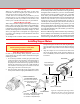
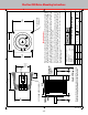
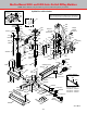
STEPPER MOTOR MOUNT
1998-09
67102
SHERLINE PRODUCTS, INC.
1°
JOE MARTIN
JOE MARTIN
JOE MARTIN
1 of 1
1 = 1
BLACK ANODIZE
3 5/16 ROUND 6061 T6
HAND
NONE
±0.006
±0.003
FLANGE
BOSS
Optional rear
handwheel
shaft
.5 .46
2.13"
Shaft: .25" Diameter
A
0.515
1.501
1.502
FLAT
1.775
1.600
SET SCREW ACCESS HOLE
8–32 TAPPED
THRU 4 PL
1.857
1.857 2.250
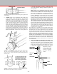
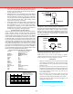
Mounting Instructions
To mount the motor, start by turning the leadscrew until the coupling set screw lines up
with the access hole in the mount. Carefully insert the motor shaft into the coupling. With
the anges touching, rotate the stepper motor until the at on the shaft is in alignment
with the coupling set screw. Tighten the set screw. Rotate the motor to align with the
motor with the 8-32 tapped holes. We usually attach the motor using three screws and
use a zip tie in the fourth hole to secure the wire bundle.
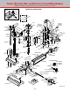
If you decide to use LocTite® on the shaft set screw, a problem can occur if the motor
has to be removed. What can happen is the shaft ends up glued to the coupling. If this
occurs, loosen the preload nut until the motor and shaft can be backed out to expose
the coupling so you can work on it. Be careful not to ex the coupling or it can break
at the dampening slots.
If using a non-Sherline stepper motor, make sure to grind flats on the shafts
as shown where the coupling and handwheel set screws contact the shaft.
FIGURE 90
Sherline CNC Motor-Mounting Instructions