
Data Sheet

-42-
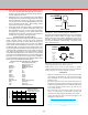
A Few More Tips
When in use, shield the unit from chips so they don’t
accumulate around the telephone jack connections on the
side. Do not use an air hose to clean the unit.
A metal stand is now included with your DRO so you can
stand the unit up on your workbench. This makes it easier
to read while you work. If you wish to secure the box to the
stand, a piece of double-sided foam tape is a good method.
Getting the Most out of Your DRO
When using a machine equipped with a digital readout, we
nd it is best to use either the readout or the handwheels,
but not both. If the displayed accuracy of .0005" (.01mm)
is satisfactory for the job you are doing, use just the digital
readout and disregard the handwheel settings. In cases
where you might want to interpolate to a higher degree
of accuracy, the markings on the handwheels will allow
you to do this.
An example of this would be where you have located the
center of a bored hole and then changed the table position.
To return the spindle exactly to the hole’s center again using
the digital readout could leave you a few ten-thousandths
o, which may not be acceptable. In this case, you should
write down your handwheel settings and direction the
handwheel was last turned before moving from the desired
location. This will allow you to return to the same spot
with great accuracy. The handwheel marks are .001" or
.01mm apart. By reading the space between the marks on
the handwheel and interpolating your position, you can
achieve a high degree of accuracy. Knowing your machine
is an important part of achieving this kind of accuracy, and
as you get more familiar with your machine, your accuracy
will continue to improve.
Sherline’s DRO brings modern machine shop technology
down to tabletop size and makes your Sherline tools easier
and more fun to use. We think you will nd the digital
readout to be a great addition to your Sherline machine shop.
Installing Stepper Motors
CAUTION!
Read all operating instructions carefully before
attempting any machining operations.
12050
8-32 x 3/8" SHCS
67127
STEPPER MOTOR
67105
COUPLER w/ 40520 SET SCREW
67102
STEPPER MOTOR MOUNT
Use fourth Socket Head Cap
Screw here or use tie wrap to
attach wires at this corner.
CABLE CONNECTOR
HOLES FOR MOUNTING TO MACHINE
(Holes on top as shown for mill X-axis and
lathe crosslide and leadscrew. Holes on
bottom for mill Y-axis.
PRELOAD NUT
Lathe Leadscrew—67104 (RH 1/4-28 for inch and metric))
X-axis and crosslide—67106 (67108 metric)RH
Y-axis and leadscrew—67107 (67109 metric) LH
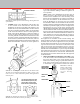
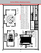
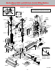
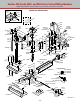
Figure 86—Components of the stepper motor
and mount. The motor can also be mounted
with the electronic cable facing downward.
67111
8-32 x 7/8" SHCS
67115
5-40 x 7/8" SHCS
67120
BALL BEARING
are tightened against the at on the shaft. Tightening the
set screw against the round part of the shaft can gall the
shaft and make it impossible to remove from the coupling
later.
3. Align the coupler set screw with the access hole in the
side of the stepper motor mount and assure that the set
screw is suciently released so that the motor shaft can
be inserted.
Stepper Motor Installation Instructions
In order to prevent damage during shipment, some of the
stepper motors have not been installed. Install them using the
following procedure:
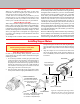
1. If not already installed, carefully plug the white cable
connector into the slot in the motor. Orient the motor so
the plug is either on the right side or on the bottom to
keep chips and coolant from causing a possible electrical
short at the connection. If you wish, a small amount of
silicon sealant or hot melt glue can be used to secure the
white plug to the motor and seal the joint.
2. Note the location of the ats on the stepper motor shaft.
Always assure that the coupling and handwheel set screws
TIE WRAP IN 4th MOUNTING HOLE