
Data Sheet

-29-
little as you need. The price per inch is somewhat higher than
industrial rates, but the convenience and overall savings make
it well worth it. There are several suppliers listed on Sherline’s
website. Your local scrap yard can also be a good source for
raw materials at good prices. Bring your own hacksaw, and be
aware that the some yards are better than others at identifying
and organizing the materials. If you are not sure exactly what
kind of metal you are getting, you could be letting yourself
in for a lot of trouble when you start cutting. See sherline.
com/raw-materials/ for a list of sources for obtaining raw
material in small quantities.
Three Types of Work
There are three basic types of work that can be performed
with a vertical milling machine: milling, drilling and boring.
It would be extremely dicult to determine whether a
vertical mill or a lathe would be the most valuable machine
in a shop. Theoretically, most vertical mills are capable of
reproducing themselves with standard milling accessories
such as a rotary table and centers. This would be impossible
on a lathe without exotic modications and attachments.
These instructions briey describe standard vertical mill work.
Several comprehensive books are available on this subject,
and, although the machines they describe are much larger, the
principles remain the same. A good starting point is a book
we oer called Tabletop Machining. It is printed in full color
and is available through Sherline as P/N 5301. Sherline tools
are used throughout in all the setups and examples.
Types of Milling Cutters
Milling on a vertical mill is usually accomplished with end
mills. These cutters are designed to cut with both their side
and end. (See Figure 64, Page 32.) Drilling is accomplished
by raising and lowering the entire milling head with the
Z-axis feed screw. Center drills must be used before drilling to
achieve any degree of accuracy. (See Figures 55 and 70.)Note
that subsequent holes may be accurately “dialed in” from the
rst hole by using the calibrated handwheels. Each revolution
of the wheel will yield .050" of travel or 1mm for the metric
machines. There is no need to start with the handwheel at “zero,”
although this can be easily accomplished with the optional
resettable “zero” handwheels to make calculations easier.
Boring is a method of making accurate holes by rotating a
tool with a single cutting edge, usually in an adjustable holder
called a “boring head.” It is used to open up drilled holes or
tubing to a desired diameter. (See Figure 57.)
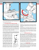
Another type of milling is performed with an adjustable y
cutter, which may be used for surfacing. For maximum safety
and rigidity, the cutting bit should project from the holder no
further than necessary. A 1-1/2" diameter circle of cut is quite
ecient, and multiple passes over a surface should overlap
about 1/3 of the circle size. For machining aluminum, use a
speed of 2000 RPM and remove about .010" (0.25 mm) per
pass. (See Figure 68 on page 34.)
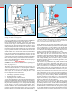
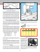
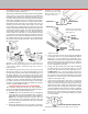
Standard Milling Versus Climb Milling
It is important to understand that the cutting action of a milling
cutter varies depending upon the direction of feed. Study the
relationship of cutting edges to the material being cut as shown
in Figure 57. Note that in one case the tool will tend to climb
onto the work, whereas in the other case the tool will tend
to move away from the cut. The result is that climb milling
should normally be avoided except for very light nishing cuts.
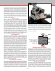
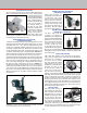
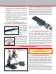
FIGURE 56—A complex setup shows a part held in a 3-jaw
chuck, which is mounted to the rotary table, which is mounted
to the tilting angle table, which is in turn mounted to the mill
table. A mill arbor holds a gear-tooth cutter which is cutting
teeth in a bevel gear. The horizontal milling conversion is used
to mount the headstock in the horizontal position. With Sherline
tools and accessories, the parts you machine are limited only by
size, not by complexity.
Climb Milling Advantages and Drawbacks
Though you will almost always use conventional milling,
climb milling can create a better nish in two ways. First, the
lightest part of the cut is at the end of the cut. Second, the chips
are tossed from the cutting area and do not aect the nish.
The major problem with machining in this direction is that
the cutter may actually do just that—climb up on the part and
break. Also, when a climb cut is rst started, the work has
to be pushed into the cutter. Then the cutting action pulls the
backlash out of the table leadscrew, and a heavier cut is taken
than planned. If you understand and compensate for these
drawbacks, climb milling can be used. However, for those
new to milling, it is best to try and plan your cuts so that the
end mill is cutting in the conventional manner.
Working to Scribed Layout Lines
A common practice when working with a mill is to lay out the
hole centers and other key locations using a height gauge and
a surface plate. A coloring (usually deep blue) called layout
uid or “Dykem” is brushed or sprayed on a clean surface
of the part. A thin layer is best because it dries quicker and
FIGURE 57—Standard
vs. climb milling. For
clarity, imagine the
cutter is moving rather
than the part.
PART
FEED
R
O
T
A
T
I
O
N
TOP VIEW
STANDARD
MILLING
CLIMB
MILLING