
Data Sheet

-26-
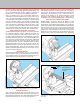
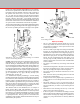
Do Not Overtighten the Chuck!
Use only moderate pressure with the spindle bars (P/N 40580)
supplied.
NOTE: Do Not Turn the Lathe Spindle On Without Having the
Chuck Jaws Tightened on Themselves or a Part!
The acceleration of the spindle can cause the scroll to open
the chuck jaws if not tightened!
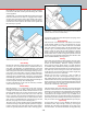
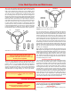
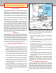
FIGURE 51—Jaw locations and identication.
FIGURE 52—Reversing the chuck jaws.
NOTE: Always start with position “A.”
REVERSED JAW
IDENTIFICATION
1ST
1ST
2ND
2ND
3RD
3RD
A
B
JAW LOCATION
STANDARD JAW
IDENTIFICATION
1ST
1ST
2ND
2ND
3RD
3RD
A
B
C
C
JAW LOCATION
3-Jaw Chuck Operation and Maintenance
The 3-jaw self-centering chuck is the most popular of all the
accessories available for the Sherline lathe. It is available in
both 2-1/2" diameter (P/N 1041) and 3-1/8" diameter (P/N
1040). These chucks will grip round or hexagonal work quickly,
since the jaws move simultaneously to automatically center
the work being held. The jaws on the chuck are designed so
that the same chuck can be used for both internal and external
gripping. Jaws are reversible for holding larger diameter work.
Due to the nature of the design of a 3-jaw chuck, it cannot be
expected to run perfectly true. Even 3-jaw chucks costing ve
times more than the one made for this lathe will have .002"
to .003" runout. If perfect accuracy is desired in a particular
operation, the use of a 4-jaw chuck is recommended. Each jaw
is adjusted independently so parts can be centered with total
precision. Both a 2-1/2" and 3-1/8" 4-jaw chuck are available
for the Sherline lathe as P/N 1044 and P/N 1030 respectively.
The 2-1/2" 3-jaw chuck (P/N 1041) is designed to take up to
1-3/16" (30 mm) diameter stock with the jaws in the normal
position. The 3-1/8" 3-jaw chuck (P/N 1040) is designed to
take up to 1-1/2" (38 mm) diameter stock. For larger diameter
work, reverse the jaws (See Fig. 52). To prevent permanent
damage, nished, turned or drawn stock should only be held
with this chuck. For rough castings, etc., use a 4-jaw chuck.
To reverse the chuck jaws, rotate the knurled scroll until the
jaws can be removed from the chuck body. After the jaws are
removed, they can be easily identied by the location of the
teeth in relation to the end of the jaws. (See Figures 51 and
52.) To maintain chuck accuracy, the 2nd jaw must always be
inserted in the same slot even when the jaws are reversed. This
slot is identied by the laser engraved letter “B” next to the
slot. Always insert the jaws in the order and location shown on
the drawings. Turn the scroll counter-clockwise when viewed
from the face of the chuck until the outside start of the scroll
thread is just ready to pass the slot for the rst jaw. Slide the
rst jaw as far as possible into the slot. Turn the scroll until
the rst jaw is engaged.
Due to the close tolerances between the slot and jaw, the most
dicult part in replacing the jaws is engaging the scroll thread
and rst jaw tooth without binding. Therefore, never use force
when replacing the jaws, and, if binding occurs, back up the
scroll slightly and wiggle the jaw until it is free to move in the
slot. Advance the scroll and repeat for the second and third
jaws. The scroll thread must engage the rst tooth in the rst,
second and third jaws in order.
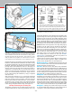
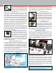
Removing a Stuck Chuck from the Spindle
Use one tommy bar in the hole in the spindle and another tommy
bar in a hole in the chuck body to achieve enough leverage
to unscrew the chuck (counter-clockwise) from the spindle
thread. If the chuck becomes stuck on the spindle thread, put
a tommy bar in the hole in the chuck body. Place a block of
wood against the tommy bar where it enters the chuck. With
a small mallet, give the block of wood a sharp tap, turning
the chuck in a counter-clockwise direction. It should not be
necessary to hold the spindle, as its inertia should be sucient.
(Don’t hit the tommy bar anywhere other than right where it
enters the chuck or you could bend it.) This small but sharp
force at the outer edge of the chuck should break the thread
loose and the chuck can then be unscrewed by hand.
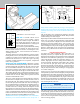
Vertical Milling Machine Operation
CAUTION!
Read all operating instructions carefully before
attempting any machining operations.
NOTE: See pages 3 through 18 for setup, lubrication and
general machining instructions. Read Safety Rules for Power
Tools on page 2 before operating any machine.
General Description
At rst glance, a vertical mill looks similar to a drill press,