
Data Sheet

-23-
If the tool chatters, rst check to see if the work is being held
properly. Then decrease speed (RPM) or increase feed rate or
both. Once the blade has chattered, it leaves a serrated nish
that causes more chatter. Sometimes a serrated nish can be
eliminated by stopping the spindle, adding a liberal amount of
cutting oil, bringing the blade up so there is a slight pressure
on it without the spindle turning, and then turning the spindle
by hand or as slowly as possible with the speed control.
Very small work may be completely cut o when held in a
chuck and allowed to fall onto the crosslide. It is too small
and light to cause any damage. Hollow articles, such as
rings, may be caught on a piece of wire whose end is held in
a suitable position.
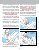
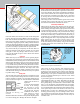
Side Tools
While these may be, and often are, used as general purpose
turning tools, their specic use is for facing the sides of collars
and shoulders; that is, nishing these to correct dimension and
with a smooth, at surface. They are also for facing work held
on a faceplate or in a chuck. The facing of work in this manner
is very useful for the production of truly at surfaces and for
producing articles to an exact thickness. The uses of side tools
are illustrated in Figures 40 and 43. The sharp corner at the
cutting point should not be slightly rounded, as may be done
with the normal turning tool, as knife tools may be required
to produce sharp corners.
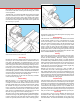
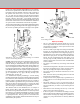
Boring Tools
The use of this tool requires the existence of a drilled or cored
hole, or it may be used to enlarge the bore of a tube. The work
must be mounted in a chuck or on a faceplate and the boring
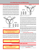
tool set as shown in Figure 41. Note the clearance behind the
cutting point as shown in
Figure 45.
A slow rate of feed should
be used, as the turnings
are not able to escape
freely from the hole and
can jam the tool. Frequent
withdrawal of the tool to
allow turnings to escape
may be necessary. Care
should be taken not to feed the tool beyond the depth required
or to feed so deeply as to damage the chuck or faceplate.
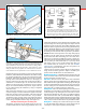
FIGURE 44—A parting tool used to separate a part from it’s
bar stock.
Where a hole must be bored right through the work, it should
be shimmed out from the faceplate to provide clearance for the
tool to feed through. The leadscrew handwheel graduations
can be used to indicate the correct depth at which to stop the
feed. Notice that, with boring, the depth of cut is increased
by moving the tool and crosslide towards the operator and
not away as with normal turning.
The boring of holes often necessitates greater than normal
overhang of the tool from the tool post, so the depth of cut
and rate of feed should be reduced from normal.
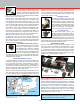
Inserted Tip Carbide Tools
Sherline brings the home shop machinist into the space age
with cutting tools that add a new dimension to small lathes.
When working with tough metals, high-speed steel tools need
constant sharpening and have a relatively short life. Brazed
carbide tools cut great but chip easily. Inserted carbide cutting
tools are the answer and have replaced those other tools in
the modern machine shop. Carbide inserts have the ability to
consistently give good nishes and long tool life at a much
higher cutting speed. This is especially important with small
lathes, because they do not have excessive power at low
RPM. With inserted carbide tools you can cut stainless steel
at the same RPM you were formerly using to cut aluminum
with high-speed steel tools without any sacrice in quality
in surface nish.
These tools are more expensive than high-speed steel,
however, they are worth every penny if you have problems
grinding your own steel tools or are cutting exotic materials
like stainless steel. Sherline oers a tool post (P/N 7600) that
holds the larger 3/8" square tool shanks used to hold carbide,
ceramic or diamond inserted tips. It also has a 3/8" round
hole for boring tools.
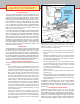
A good starting point for an inserted tip tool is the P/N 2256
right-hand holder with a 35° oset. This holder uses the P/N
7605 carbide insert, which is a 55° insert good for turning,
facing and proling. A left-hand tool is also available as P/N
2257, or a set of both left- and right-hand tools is P/N 2258.
Tools are also available to hold 80° inserts, which are slightly
less versatile but oer longer tool life because of their stronger,
more square shape. These tools should not be used to cut
hardened steels or piano wire. Materials such as those are
normally ground to shape, not cut, although ceramic inserts
can sometimes be employed to cut these materials. Abrasive
materials such as glass-reinforced plastics can be easily cut
with these tools.
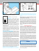
FIGURE 46—Carbide insert tool and tool post. The tool post
holds both 3/8" square and round tools.
P/N 2256 TOOL HOLDER
CARBIDE INSERT
P/N 7600 TOOL POST
FOR 3/8" INSERT
HOLDERS AND 3/8"
ROUND BORING
TOOLS
A SPECIAL TORX DRIVER
FOR TIGHTENING THE
INSERT HOLD-DOWN
SCREW IS INCLUDED
WHEN CARBIDE TIPS
ARE PURCHASED
CLEARANCE
FIGURE 45—Boring tool
clearance