
Data Sheet

-22-
TOOL
PART
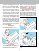
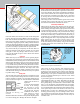
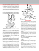
FIGURE 41—A boring tool in use on the lathe
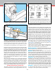
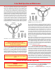
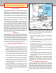
FIGURE 43—Arrows show direction of tool feed in all diagrams.
SIDE TOOLS
NORMAL TOOL
SLIGHTLY
ROUNDED
CORNER
LEFT-HAND
TOOL
RIGHT-HAND
TOOL
CLEARANCE
CLEARANCE
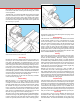
Form Tool—A custom contour can be
ground into a tool to produce a special
shape like a radius in a part. The width of
the cutting edge must be less than 2-1/2
times the smallest diameter. Cutting speed
must be slow to prevent chatter.
The clearances ground behind the cutting
edges indicate the type of material for which the tool may
be used and the direction in which it is fed along the work.
When grinding tool bits, correct clearances are essential or
“rubbing” can occur.
The shape shown here would be dicult to grind on a home
bench grinder, however, the same form could be achieved by
grinding two separate tools with half the needed arc on the
outside corner of each tool–a “left” and a “right.” By using
a number of simple shaped tools in sequence, complicated
forms can be generated.
Turning Tools (Left- and Right-Hand)—Reference to Figure
43 will illustrate the lateral positioning of this tool. Note the
clearance behind the point between the end of the tool and
the work. Insucient clearance will cause the tool to “rub,”
and excessive clearance will produce a ridged or wavy nish
due to the small length of tool edge in contact with the work.
This ridging becomes more pronounced with rapid feed. To
provide a smooth nish, the sharp cutting point may be slightly
rounded with an oil stone, taking care to preserve the side
clearance underneath this corner.
This type of tool should not be advanced directly end-wise
into the work. The depth of cut is set while the tool is clear of
the end of the work. The starting procedure is to advance the
tool until the point just touches the work. Note the reading on
the crosslide handwheel, withdraw the tool slightly and move
along until clear of the end of the work. Now advance the
crosslide to the above reading, add desired depth of cut and
then feed the tool along the work piece the desired distance.
Withdraw the tool clear of the work, having noted the reading
on the crosslide handwheel. Mentally note the reading on the
leadscrew handwheel, return the tool to starting position and
advance to the previous reading plus the desired cut.
NOTE: Sherline oers optional adjustable “zero” handwheels
that allow you to reset the handwheel to zero at any time...a
handy feature normally found only on larger, more expensive
machine tools. New tools may be ordered with them already
installed, and existing tools can be retrotted with them on
any axis.
The second feed is now commenced, stopping at the same
reading on the leadscrew handwheel as before. This procedure
enables turning to accurate length.
Repeat the procedure until the work has been reduced to within
about .010" (0.25 mm) of desired diameter, noting that each
.015" (0.4 mm) increase in depth of cut will reduce the work
diameter by twice this amount; that is, .030" (0.8 mm). For
the nishing pass, advance the tool by the required amount
and feed along the work just far enough to gauge the nished
diameter. Adjust depth of cut if necessary and complete the
nal pass using a SLOW feed to obtain a smooth nish and
exact size.
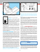
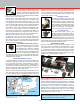
Using the Cutoff or Parting Tool
(See Figure 44.) After completing a part in the lathe, it is
frequently necessary to separate the part from the excess
material used for chucking. This operation is best accomplished
with the use of a cuto tool or “parting tool” as it is sometimes
called. The Sherline cuto tool and holder utilizes a very
slender, high-speed tool steel cutting blade mounted in a
special tool holder. The thinness of the blade (.040") enables
it to feed into the part quite easily and at the same time
minimizes the amount of waste material. A word of caution:
Never use a parting tool on a part mounted between centers.
The part may bind on the cutter, resulting in a scrapped part
or a broken cutting tool.
Always try to lay work out so the cuto tool is used as close
to the spindle as possible. Set blade height by sliding the blade
back and forth in the slightly angled slot in the tool holder. It
should be set so the tip is aligned with the centerline of the
part being cut. An unusual diameter may require a shim under
the front or rear of the holder to accomplish this. The tool can
also be mounted on the back side of the table by using the
rear mounting block, P/N 3016.
IMPORTANT!
Always use cutting oil when using the cuto tool. The
cut will be made much smoother, easier and cooler.
The turning speed for parting should be about one-half the
normal turning speed, and feed rate should be a little heavy
so the chip will not break up in the slot. If speed and feed are
correct, there will not be any chatter, and the chip will come
out as if it were being unrolled. Cutting oil plays a major roll
in this occurring properly.
FIGURE 42—Form tool and part