
Data Sheet

-7-
bottom of the base. Hand-turn the rst screw part way in, and
then start the second screw. This can be done with the machine
upright by letting the base hang over the edge of your table or
bench just far enough to expose the rst hole. Using the large
3/16" hex key provided, snug up both screws lightly rst, and
then tighten evenly.
2000- and 5800-Series Mills—Assembling and Mounting
the Multi-Direction Column
To assemble the multi-direction column, make reference to the
exploded view on pages 49 through 52 of these instructions
and complete the steps that follow:
1. Attach the round column base (P/N 56700) to the mill
base with the two 1/4-20 x 1-1/2" socket head cap screws.
2. Screw the arm hold-down bolt (P/N 56130) into the top
of the round column base and tighten with an adjustable
wrench using the two at indentations on the shaft.
3. Slip the round column top (P/N 56550) over the pin and
rotate it until the at sides are parallel to the mill base
and the engraved degree lines are on the same side as the
X-axis handwheel.
4. Using an 11/16" or a 17 mm wrench, loosen the ange nut
holding the bed and swing arm together. Rotate the bed
away from the swing arm until they are at approximately
a 90° angle to each other. Retighten the ange nut rmly
to hold the column in this position. Discard the protective
wood spacer that was installed between the bed and arm
during shipping.
5. Set the swing arm over the column and align it approximately
square with the mill base and in about the center of its
travel. Make sure the swing arm registers on the ats of
the column top and is properly seated. While still holding
the swing arm unit in place, set the hold-down washer
(P/N 56200) over the end of the bolt. Put a ange nut on
the end of the bolt and tighten it against the hold-down
washer rmly to lock the swing arm in place. NOTE:
There should be NO lubrication on the mating surfaces
between the arm and the column base. Friction between
these surfaces keeps the arm from moving during cuts.
6. Place the column adjustment block (P/N 56350) on top of
the swing arm and attach it with two 10-32 x 5/8" socket
head cap screws at both ends. Adjust the 1" long center
bolt so that it is just touching the at in the bottom of the
relieved section in the top of the pivot knuckle when the
column is in the 90° position.
NOTE: If you remove the column adjustment block to
accommodate a backward tilt movement of the column,
make sure you replace it when returning the column to
an upright position. It not only serves as a reference point
when returning the column to the 90° position, it also
keeps it from accidentally swinging down and damaging
the table if the ange nut is loosened.
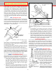
7. Slip the alignment key into its keyway in the mill saddle.
Place the assembled headstock/motor/speed control unit
(See next section) over the pin on the mill saddle and over
the alignment key. Tighten the set screw in the side of the
headstock to hold the entire unit in place. Recheck to be
sure you have tightened the ange nut on the shouldered
bolt pivot pin (56210) securely so that all the weight of the
column is not resting on the column adjustment block bolt.
Mounting the Motor and Speed Control Unit
to the Headstock
(Refer to Figure 13 on the following page, and the exploded
views on pages 45 through 52 for part number references.)
In order to keep shipping costs and damage to a minimum, all
new Sherline machines are shipped with the motor and speed
control disassembled. The same power unit assembly is used
on all Sherline lathes or mills, so these instructions apply to
all machines (Video instructions available on sherline.com).
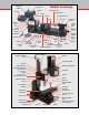
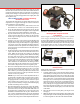
FIGURE 9—Components ready for assembly.
Assembly Procedure
Gather all the needed components as shown in Figure 9 above.
Assemble them as follows:
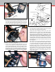
1. Using the small hex key, remove the motor pulley from the
motor shaft by loosening its set screw. Place the inner belt
guard against the motor and secure it using the two hex
aluminum standos (P/N 43100). There are four threaded
holes in the motor. Use the pair that aligns with the brush
housings so the cord to the speed control housing points
downward as shown. (See Figure 10.) Reinstall the motor
pulley (P/N 43360) to the motor shaft and tighten the set
screw, making sure it engages the at on the motor shaft.
The end of the pulley should be even with the end of the
motor shaft with the smaller pulley toward the outer end
of the shaft.
2. Place the drive belt over motor pulley. (See Figure 10 on
next page.)
3. Make sure the drive belt is routed properly. Then set the outer
belt guard in place on the inner belt guard, locating the holes
in outer belt guard over the ends of the motor standos.
FIGURE 8—The assembled power unit.