
Data Sheet

-30-
won’t chip when a line is scribed. The purpose of this uid is
to highlight the scribed line and make it easier to see.
Don’t prick-punch the scribed, crossed lines representing
a hole center. Using a center drill in the mill spindle and a
magnifying glass, bring the headstock down until the center
drill just barely touches the scribed cross. Examine the mark
left with a magnifying glass and make any corrections needed
to get it perfectly on center. You should be able to locate the
spindle within .002" (.05 mm) of the center using this method.
Once the rst hole is located in this manner, the additional
holes can be located using the handwheels. (This is where the
optional resettable “zero” handwheels are useful.) Now the
scribe marks are used as a double check and the handwheels
take care of the accuracy. Don’t forget the rules of backlash—
always turn the handwheels in the same direction as you go
from one point to the next.
Using a Dial Indicator
(NOTE: For more on use of a dial indicator to square up your
mill, see pages 13-16.)
The basis of most accurate machining involves the use of a
“universal dial test indicator”; a small, inexpensive indicator
which is calibrated in .001" or .01 mm divisions. An indicator
with a large face or one that reads in ner divisions is not
necessary for use with this mill. Three major tasks that can
be accomplished with an indicator are:
1. Checking the squareness of a setup.
2. Finding the center of a hole.
3. Aligning the work with the machine.
A vise can be mounted or a part can be clamped down exactly
parallel with the machine slides by holding the test indicator
stationary and moving the slide with which you wish to align
the part. When “indicating in” a vise, always take the reading
on the xed jaw. To start with, use approximately .005"
indicator deection from neutral. Remember that excessive
pressure can cause inaccurate readings. Also, try to keep the
indicator nger at a reasonable angle to the indicated part or
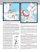
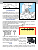
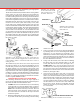
FIGURE 59—Indicating in the jaws of a vise. Shown is a Starrett
“Last Word” Indicator. Starrett gauges are available in numerous
sizes and types. They are manufactured in Athol, Massachusetts
and can be purchased from most industrial dealers.
surface. When the part is properly aligned, there will not be
any deection on the indicator. If you wish to locate the spindle
over an existing hole, place the indicator in the spindle and
read the inside surface. Move the X- and Y-axes until there
is no deection when the spindle is rotated. At this point, the
spindle is in perfect alignment with the hole’s center.
When aligning the spindle to used bearing holes, remember
that the hole may be worn out-of-round, and it may be
impossible to attain zero indicator deection reading. Boring
out a worn bearing hole to a larger diameter and sleeving it
with a simple bushing made on a lathe is a fairly common
machining operation. With the new bushing pressed in, the
bearing will be like new.
The squareness of your machine may also be checked with
an indicator. For instance, alignment of the head can be
checked by osetting the indicator in the spindle so the tip
will move on about a 3" to 5" diameter circle. The amount of
reading relative to the table is the amount of error. Don’t be
discouraged to nd a few thousandths of an inch error in your
machine. This machine has been designed to have the most
accuracy commensurate with reasonable cost. In machine
tool manufacturing, accuracy and cost run hand-in-hand. To
increase accuracy only a few percentage points could double
the selling price, because entirely dierent manufacturing
processes would be required. However, you can personally
improve the accuracy of your machine with a few shims, if
needed, by employing your dial indicator.
The column bed is aligned with the column block at the
factory. If you remove the block, it will have to be realigned
by mounting a known “square” on the mill table and adjusting
placement of the bed by running an indicator on the square
as the headstock is raised and lowered. (See Figure 29, page
16.) The same method can be used to check alignment of the
column bed to ensure it is square with the Y-axis. To correct
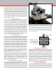
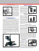
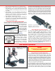
FIGURE 58— Boring the inside of a hole to exact size with a
boring tool held in a boring head.