
Data Sheet

-27-
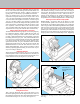
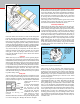
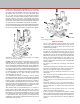
but there are some important design dierences; for example,
the mill has a spindle that can take side loads as well as end
loads and an accurate method of moving work in relation to
the spindle on all three axes. It is wise to memorize these
“X,” “Y” and “Z” axes, because, since the advent of complex
electronically controlled milling machines, these terms have
become common “shop talk,” even outside engineering
departments. Feed screws with calibrated handwheels control
movements on these three axes. The handwheel calibrations
are quite accurate and should be used whenever possible.
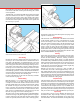
Angles can be machined by removing the headstock alignment
key and rotating the milling head to the appropriate angle to
the work or by holding the work at an angle to the spindle.
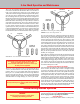
FIGURE 53—The axes of movement for milling on a standard
3-axis vertical milling machine.
X
Y
Z
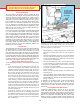
FIGURE 54—Eight directions of movement of the model 2000
series milling machines.
1 (X-axis)
2 (Y-axis)
3 (Z-axis)
4
5
6
7
8
Helpful Tips for Milling
• This is a small, light-duty mill and should not be used to
remove large amounts of stock that could be easily removed
with a hacksaw. For eciency, select a piece of stock as close
to nished size as possible.
• Stresses on a mill are quite high when cutting most materials;
therefore, gib and backlash adjustments must be properly
maintained. (See “Adjustments” section beginning on page 11.)
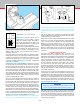
• End mills must run true and be sharp. Holding end mills in a
drill chuck is a poor practice. Use collets or an end mill holder
instead. The 3/8" end mill holder (P/N 3079) allows you to
use a large range of readily available 3/8" end mills with your
machine. (Several other size inch and metric end mill holders
are also available.)
• Fly cutting is an excellent way of removing stock from at
surfaces.
• Normal machine alignment is adequate for most work, but if
the work is exceptionally large or requires extreme accuracy,
shims may be employed to improve machine alignment.
• For accurate setups you should have and know how to use a
dial indicator.
• Often, more time will be spent making xtures to hold work
than doing the actual machining.
• To help save time on many simple setups, a good mill vise is a
must. A drill press vise is not designed for the forces involved
in milling.
• Plan ahead. Always try to have one point from which to
measure. Do not machine this point o part way through the
job. This would leave you with no way of measuring the next
operation.
• Remember the basic machining rule that says: “If the tool
chatters, reduce speed and increase feed.”
• It takes a long time to accumulate the knowledge, tools and
xtures required for many dierent types of milling operations.
Do not become discouraged by starting with a job that is too
complex or by using materials that are extremely dicult to
machine.
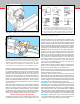
(NOTE: Lighter than normal cuts should be taken when the
alignment key is not in place.) The latter method must be
used for drilling on 5000/5400-series mills to keep the drill
movement parallel with the machine slide. Angle drilling can
also be accomplished without removing the alignment key
by using the optional rotary column attachment (P/N 3500).
(The Model 2000 mill is also capable of angle drilling due to
its multi-axis design.) All machine slides have an adjustable
gib to compensate for any “play” that may develop. (See
“adjusting gibs” on page 12.)
It is assumed that anyone purchasing a vertical milling
machine has had some experience working with metal cutting
tools; therefore, these instructions are somewhat limited for a
beginner. There is enough information, however, to enable a
good craftsman to get started. Using a vertical mill correctly
takes more skill and experience than is required for lathe
operation because of the additional axis (vertical) and the
more varied type of work that can be performed.
The machine must be well maintained, for it is subject to
higher stresses than a lathe. This particular mill is one of
the smallest being manufactured and is an extremely useful
tool. However, it would be unreasonable to clamp a 3-pound
piece of stainless steel to the work table and expect to make
a 1-pound part from it. The key point is to work within the
capabilities of the machine, and those limitations can only be
determined by the operator.