
Data Sheet

-19-
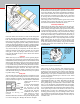
Inducing Chatter and Learning How to Overcome It
To better understand what is going on, we will now purposely
try to make the machine “chatter.” Make sure the stock you
are cutting is sticking out of the chuck no more than 1 inch
(25 mm). Crank the handwheel two turns further in from the
last setting which will give you a .100" (100 thousandths of an
inch) or 2 mm cut. Set the spindle speed to about 1000 RPM
(1/3 speed) and feed the tool slowly into the material. Vary
speed and feed until you get a substantial chatter. Without
changing the depth of the cut, drop the speed to about 200
RPM and feed the tool into the work with more force. The
chatter should disappear. Once you have learned to control
chatter by adjusting speed and feed, you will be well on your
way to becoming a machinist.
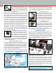
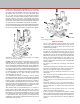
Holding the Workpiece
Work can be held between centers, in 3-jaw or 4-jaw chucks,
on the faceplate or with a collet. Sometimes it is necessary to
use a chuck and center, and, if the work is spinning fast, a live
center should be used. (See Figures 33, 34 and 35.)
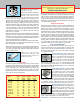
would be similar to tearing an individual sheet of paper o
the roll. The results when cutting metal would be shorter tool
life, a poor nish and tool “chatter.” Chatter is a function of
rigidity, but it is controlled by speed (RPM) and feed rate.
Since you already have a piece of aluminum chucked up,
experiment with speed and feed rate. You just took a cut of
.010" (.25 mm) and probably noticed that the machine didn’t
even slow down in the slightest. Now take a 1/2 inch long cut
.050" or 1 mm deep, which is one complete revolution of the
handwheel. If you used the sharpened cutting tool that came
with your machine, it should have made the cut easily. If the
tool “squealed,” reduce the RPM a little and take another
.050" cut while feeding the tool faster. You will probably be
surprised at how easily your machine takes cuts this heavy.
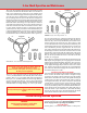
Turning Between Centers
This is done by tting the dog to the work which is to be
turned and placing the work and dog between the centers in
the headstock and tailstock. The maximum diameter that can
be held with the dog is 5/8" (15 mm). (See Figure 35.)
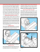
FIGURE 33—Holding a round work piece in a 3-jaw chuck.
The dog is driven by tting it into one of the faceplate holes.
This method of turning is ideal for bar work or turning of
steps on a bar. The tailstock center must be greased to prevent
overheating. (An optional live center—such as P/N 1191—
turning on ball bearings is the solution preferred by most
machinists.) The headstock spindle has a #1 Morse taper in
the spindle nose. The tailstock spindle has a #0 Morse taper.
Removing Tools from the Morse Taper Spindles
HEADSTOCK—Accessories held in the Morse #1 taper
of the headstock spindle can be removed with the use of a
knockout bar (not supplied) approximately 3/8" in diameter
and 6" long. The bar is inserted through the back of the spindle,
and accessories, such as centers, can be removed with a few
taps. Accessories like the drill chuck that are drawn into the
spindle taper with a drawbolt are removed by loosening the
drawbolt a few turns and then giving the head of the bolt a
sharp tap with a mallet to break the taper loose. Supporting
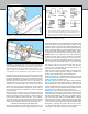
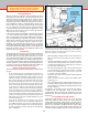
FIGURE 34—Holding a square work piece in a 4-jaw chuck.
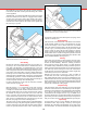
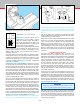
FIGURE 35—Turning between centers with a faceplate and
drive dog.
DOG
FACEPLATE
Grease tailstock center to
prevent overheating or use a
“Live center.”