
Instructions
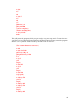
x-1.910
y1.910
x-.090
y.100 z-.150
x-1.900
y1.900
x-.100
y.100
x-.200 y-.200
g00 g40 z1
x1 y0 z1
m2
%
Nothing worth commenting about in that program except that my final move before
canceling cutter comp was to eliminate a burr that would have formed if I had gone
straight out, and you should be able to figure rest it out yourself. What you can do is set
the value of d1 at a very small diameter and run the program through. Then set the d1 at
the true diameter of the cutter used and you can see the shape of the part and then the
cutter path followed using g41. Notice how the machine goes around sharp corners. Neat!
This isn’t a bad idea to use throughout these problems to help you better understand the
process.
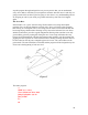
Planes that don’t fly
In the CNC world there are three different planes. They come into play when we want
our computer to do circular interpolation in a vertical plane. With this being the case,
then either the x or y coordinate will have to be predominate with the Z-axis. We can
control these with the g17 (x, y) g18 (x, z) and g19 (y, z) inputs. When we are working in
these vertical planes generating arcs and circles, the z offset for the arc center point will
be controlled by the k input, again designating the offset in the z direction given as an
incremental value. Got that?
46