
Instructions
The coming programming examples don’t use this method of bringing the cutter up to the
part because it wasn’t necessary in my examples. In the real world, this will be a problem
that you’ll regularly encounter, and you’ll have to use every trick in the book to produce
the parts that are needed.
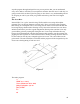
For the time being, remember that the closer you align your cutter (aircraft) with the
directional edge that you want to machine (runway) the better the landing. Remember, in
the world of CNC there is no gravity, and you can touch down any way you please.
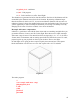
Let’s go back and add g41 to the circle program. Modify your circle program to read like
this. Refer to the drawings with examples in this section.
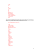
The entire program:
%
(circle using g40, g41, g42)
g00 g90 g40 x1 y1 z1
g42 d1 x.5 y1
x0
z0
g01 z-.3 f10
g03 x0 y1 i0 j-.5
g00 z1
g40 x1 y1 z1
m2
%
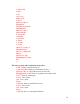
Now I’ll go through the program one line at a time
Note: Before this program can be run the tool offset has to be entered. Go to [TOOLS]
and enter 0.250" (6.4 mm) for the tool length, and 0.375" (8.4 mm) for the tool diameter.
You must use the [Enter] key after entering each change in order for the change to be
entered into the table. Close page.
1) % –Last time—Start program
2) (circle using g40, g41, g42) –Last time—Program Name
3) g00 g90 g40 x1 y1 z1 –Home
4) g42 d1 x.5 y1 –End Mill (aircraft) approaches part as tool compensation is
entered (gear down). d1 will define the offset as it moves to this new g42
position. We’re still traveling too fast for landing.
5) x0 – We’re directly above the touchdown area and come to a halt.
6) z0 – Fortunately we’re flying the new Osprey and they can come straight
down.
7) g01 z-.3 f10 –Landing speed and touchdown from a vertical plane.
8) g03 x0 y1 i0 j-.5 –We cut a quick circle just like last time and we’re out of
here.
9) g00 z1 –Straight up
44