
Instructions


I’m buying
I’m a little bored with this exercise myself so let’s drop over to route g41 and see what’s
going on. The programmers that reside on g41 are a little on the snobby side because they
think they have some special talent that us regular guys can never learn. That was
probably true when they learned it, but they didn’t have Joe Martin teaching them. In
Joe’s class no one is left behind, and let me promise you this, guys, we are going move
into their neighborhood so fast they will think we always lived there. But for the hell of
it, let’s stop by their fancy cocktail lounge and have a beer so they can get used to us. I’m
buying.
Homing your machine
Now would be a good time to slip something in about “home position,” which is the
actual x, y and z position the machine is in when you start to run your program. I will
usually have the zero points in the same location as they are on the drawing, which makes
the program easier to write without errors; however, it is seldom the actual position you’d
want your machine to be in to load or unload parts or check dimensions. The best way
I’ve found to determine the home position is to first locate the zero position. Jog the
slides to the approximate zero position and then move them manually with the
handwheels (power to the drivers turned off) to the exact position where your cut will
start. Zero the control's readout by using the "zero all axes" button. With driver power
switched back on, the slides can then be moved to a position that you believe would be a
good home position using the incremental jog feature or the MDI program. It’s a good
idea to make these whole numbers such as x2 (or 50 mm), y2 and z2 because you’ll have
to type these in when writing your program. You’ll have to be careful of having tools
loaded in the spindle and manually calling a zero position before the program has a tool
length offset loaded. This last warning will make much more sense later on in the
instructions.
Tool height offsets
Before we get too involved in the more complex cutter diameter programming, I want
you to learn how to deal with the difference in tool lengths. It is obviously simpler to
have a single zero point for all tools, and that is what the EMC2 allows you to do. The
length and diameter of each individual tool is stored in a file called “Tools,” located
along the top row of the control panel. The tool length is usually called up in the first z-
axis move using each individual tool by entering a g43 h1, 2, 3,--. The g43 tells the
computer to use the tool length (h) stored in the line (1, 2, 3,---) of the tool data file. A
g49 is entered when the z-axis is brought back to its home position to cancel out the tool
length compensation that was called up when you first started using the tool.
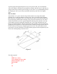
From a practical standpoint, I like to make the shoulder located behind the ¾-16 spindle
nose thread the zero point on the Sherline mill and use screw-on Sherline tool holders as
an inexpensive, quick and accurate way to change tools. If just one tool holder is used,
the cutter height must be adjusted each time it is changed. If multiple holders are used,
each with its own tool pre-adjusted to the correct height, tools can be interchanged
quickly with excellent repeatability on their height setting. There is also a holder with a
thread to accept a Jacobs 1/4" or 3/8" drill chuck, so they can also be interchanged like
end mill holders. It is P/N 3074.
41