
Instructions
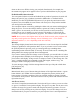
clicking the file name will also open it.) If you highlight a section of text and use the
Edit>Copy commands you can then open another program and use the Edit>Paste
commands from the menu to paste the lines of code into the new program. This editor
does not have the ability to automatically reload the program into the EMC interpreter
after a change. You will need to do that in EMC2 by selecting the file after saving it.
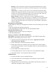
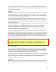
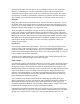
Backplot
[Backplot] will show the tool path that can be viewed from a chosen direction. “3-D” is
the default. Other choices and controls are displayed along the top and right side of the
pop-in. If you are in the middle of a cut when you press one of these control buttons the
machine will pause long enough to re-compute the view.
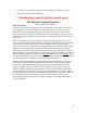
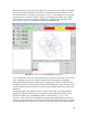
Along the right side of Backplot is the pop-in that you can display with the [SETUP]
button. This will show a small graphic that tries to show the angle you are viewing the
tool path from. Below it are a series of sliders that allow you to change the angle of view
and the size of the plot. You can rotate the little position angle display with these. They
take effect when you press the [Refresh] button. The [Reset] button removes all of the
paths from the display and readies it for a new run of the program but retains your
settings for that session.
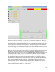
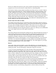
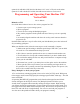
Pop-in Tool
The tool page is pretty much like the others. You can set values here and they become
effective when you press the [Enter] key*. You can’t change tool offsets while the
program is running or when the program is paused. The [Add Tools] and [Remove Tools]
buttons work on the bottom of the tool list. Once a new tool has been added, you can use
it in a program with the usual commands.
*Always use the [Enter/Return] key at the right side of the normal alpha keyboard, not
the [Enter] key at the bottom right of the numeric keypad.
Limit switches
I felt that limit switches would add an unnecessary cost to the system when using stepper
motors with limited torque such as these. They have to be mounted in areas where they
are exposed to chips, oil and coolant creating more problems than they eliminate. The
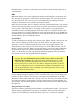
Sherline mill is fitted with “hard stop” screws on the X and Y axes that limit travel. These
stops are the heads of cap screws fitted to the table and base and positioned to stop a
runaway axis without damage. If you make a programming error that would drive the
table into a crash situation by over-traveling, the table will encounter these hard stops
before damaging the leadscrews and nuts.
You could also locate a home position from these hard stops by stalling the stepper
motors against them. Of course you should do this in manual mode and by bringing the
table against the hard stop carefully in slow speed and "buzz" the motor against it. I
personally would find a different way of locating a home position, using the dials on the
handwheels for example, but it is an option for unusual situations
It should also be noted that the hard stop screw would have to be removed from the left
underside of the table in order to have the full 9 inches of advertised X-axis travel. With
the stop screw in place travel is about 8.65". Note also that Sherline now offers an
29