
Instructions
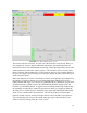
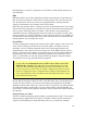

FIGURE 1.4—The control panel screen
The screen is laid out in sections. The first row is the menu bar across the top. Here you
can configure the screen to display additional information. The small buttons that are
located left center of the command indicate that they control the large blank section of the
control panel that is sometimes called a “pop-in.” This will allow you to view the editor,
plotter, tool page and coordinate page. If more than one pop-in is active (button shown as
red) you can “toggle” between these pop-ins by right clicking anywhere within the pop-in
screen with your mouse.
Below the menu line is a line of control buttons. These are the primary control buttons for
the interface. Using these buttons you can change mode from [MANUAL] [AUTO]
[MDI] (manual data input). You can also use [FEEDHOLD] or [ABORT] to stop or abort
a programmed move. When you press the [FEEDHOLD] button it changes color and
becomes a [CONTINUE] button. It toggles between running and pausing. Feedhold has
the advantage of being able to restart the program from where you stopped it. When all
else fails press a software E-Stop—the button in the upper right labeled [ESTOP PUSH].
There are two columns below the control line. The left side of the screen shows axis
position, feedrate override, and any messages that are sent by the EMC to the operator.
You can add things like current tool number and length, type of position shown, and
offsets in effect by looking under the <View> menu.
23