
Instructions


It would be difficult to describe the many combinations
that could be generated using this method, so I’ll give you
a general “overview” of the rules and leave the rest up to
your imagination.
1.) The Master controller that initiates the sequence may
be in any motion mode. Note: the controllers may be
either a linear or rotary type or a combination of both. The
difference between the two is they each have code written
specifically to control a linear slide or a rotary table.
2.) The second controller (called the “Controllee”) will
start its program when the Master program comes to a
block that is terminated with a “Pause” command or, if
it’s a rotary controller, it has completed a Division Mode
or Degree Mode movement.
3.) The Master will be restarted when the Controllee
program comes to a block that is terminated with a “Pause”
command or, if it’s a rotary controller, it has completed a
Division Mode or Degree Mode movement.
4.) When a programmed block is terminated with the
“Stop” command (entered with the [ 8 ] key at the end of
a program block), the program will stop and not trigger the
other controller. The operator must press [NXT] to continue.
It would be advisable to enter just one “Stop Command,”
and for it to be in a block in the Master controller. This keeps
the operator from having to press NXT on both controllers
to run a program.
Cutting a Gear Using All the Features of Both Linear and
Rotary Sherline Controllers
Example:
The following procedure gives you an idea of how easy it
would be to program a complex set of operations to produce
a 53-tooth gear. I chose 53 teeth because it is a prime number
and can’t be produced with simple indexing.
Linear Controller Program:
1) Rapid feed up to gear blank from home position. No
Pause
2) Slow feed across gear face with cutter. No Pause
3) Slow feed back across gear face for quality finish. No
Pause
4) Rapid feed to home position. Pause
Sherline CNC Rotary Table Controller Program:
1) Using the Division Mode, enter the number 53
With five lines of code (keypad entries) you have now entered
all the information needed to produce a 53-tooth gear. Think
about it. The slide will rapid up to the cutter, slow down
and make a cut, feed back across the part at a programmed
feed rate, and rapidly return to its home position. The rotary
table will then index, and initiate the next cut. This will
be repeated until the required 53 indexes have been made.
After the last index, the program will stop and wait for an
operator. This has been accomplished inexpensively with
a very clever design and program, and we at Sherline and
Bryan and I are quite proud of it.
Two Linear controllers could be linked to produce any
number of sequences for simple but useful movements. For
example, one controller could drive the mill table X-axis,
and the other could drill with the Z-axis.
Machining with a Rotary Table
By Joe Martin
The following instructions are included to give you some
further insight into the fine points of using a rotary table for
machining operations. Sherline Products Inc. makes a wide
variety of miniature machine tools, which now includes
the CNC rotary table (P/N 8700). For obvious reasons,
the descriptions and illustrations use these machines as
examples.
Mounting the Table to a Full-size Mill
Sherline machine tools have very limited work areas and
the tools and accessories manufactured by Sherline are
designed to be used in conjunction with one another to
eliminate wasted space. If you plan to use this device on
full-sized equipment I would suggest mounting the table to
a rectangular block of metal. There are three 10-32 tapped
holes on the bottom of the table for this purpose. The holes
are 120° apart on a 3.2” (81.28mm) bolt circle. On a Sherline
mill, the stepper motor mount overhangs the table, but on a
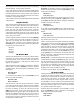
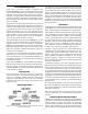
large industrial table, a
riser block is needed to
keep the motor mount
from interfering with
the table surface.
When mounted to an
aluminum block of
sufficient size (Sherline
P/N 8710), the entire
assembly can be held in
a vise in the horizontal
or vertical position,
thereby making it
easier to use. It can also be mounted on a standard Sherline
tilting angle table (P/N 3750). Remember that when operated
in an industrial environment, the unit cannot be flooded
with coolant.
Don’t let the reasonable price mislead you into believing
this is not a precision piece of equipment. During the past
thirty years, Sherline has specialized in designing and
manufacturing equipment where you, the customer, get
the most “bang for the buck.”
The following instructions have been written to show what is
involved in doing a complex job on a rotary table accurately.
In many cases these instructions have nothing to do with
how the table is driven. A CNC-driven table can solve the
problem of tedious calculations, but it will never solve an
error in logic. I believe if you truly understand the job I
will describe in detail, average jobs can be accomplished
without filling your trash can with mistakes. Remember,
there are not many people capable of making the complex
machined products used today, and if you can master the
vertical mill and the rotary table combination, you will
FIGURE 3—Rotary Table
mounted to a riser block
-9-