
Instructions


Sense and Aacknowledge Input
Some CNC controllers support a SENSE and
ACKNOWLEDGE (ACK) protocol for a fourth axis with
a “M” command. When the “M” command is executed the
controller closes a relay and then waits for the “M-FIN”
input line to go high (open circuit) while the remote device
is operating. When the remote device has finished, it must
short the M-FIN line to ground to acknowledge that the
action is complete.
The Sherline controller supports this M protocol. There is a
SENSE input line and an ACK output line in the interface
connector. The SENSE input is made active by shorting it
to ground. It is left inactive by leaving it unconnected to
ground, or by pulling it to 5 volts. The ACK output is an
“open collector” drive signal. It can be used like a switch
closure. When it is active, it will be connected to ground.
When inactive, it will be an open circuit. The ACK output
will work with signals as high as 30 volts.
The SENSE input works just like the
[NXT] key on the
controller. In either of the motion modes (Positioning or
Program) where you can move the table by pressing the
[NXT] key on the keypad, you can also move the table by
shorting the SENSE input to ground. You can use some
other CNC controller to make the SENSE input low (for
example, the M command}.
To connect your CNC controller to the Sherline controller,
add a relay to your CNC machine. Connect the relay switch
contacts to the Sherline controller SENSE and GROUND
lines. When your CNC control closes the relay, it will trigger
the Sherline controller.
Every time the
[NXT] key or the SENSE input initiate a
motion, the ACK output of the Sherline controller will be
shorted to ground. As soon as the Sherline controller has
completed the motion, the ACK output will be opened (will
not be shorted to ground).
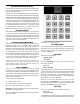
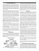
Cable Color Code
Colors of the wires inside the cable are not consistent
from batch to batch, so we cannot provide a reliable color
code. Use a continuity checker and the pin map shown
in Figure 2 to determine the color of the wire connected
to each pin. Note the colors on the chart in Figure 2 for
future reference.
Remote Trigger Switch
The controller can be operated from a remote switch. This
will allow you to keep the controller in a more “friendly”
environment and have a more durable switch used for
starting a programmed sequence. To incorporate this
feature, connect the remote trigger switch that is normally
open to the SENSE INPUT and GROUND wires of the
included 8-pin connector cord. (NOTE: The first time a
program is run, it must be initiated by hitting the
[NXT]
button on the keyboard. After that, it can be initiated from
the remote switch.)
Limit Switches
Although the use of limit switches would be unusual with
rotary tables it is a feature that’s built in for our CNC linear
tables so we thought we would bring it to your attention.
The Sherline Controller supports the use of limit switches
to avoid running a cutter into a fixture or clamp. The limit
switches should be simple “normally open momentary
contact” type switches. You can place a limit switch at each
end of the table if you wire them in parallel. Arrange the
switches so they will be closed by the motion of the table
when it gets too close to something you don’t want it to
reach. The limit switches are wired into the 8-pin interface
connector at the end of the controller. (See Figure 2.)
The limit switches will be active in all motion modes,
including the JOG mode. When the controller moves into
a limit switch, it will remember that it cannot move any
farther in that direction. The controller will consider the
move complete. Any further commands to move in that
direction will also “pretend” to execute, but no actual
motion will take place. Instructions to move in the opposite
direction will work fine.
This feature will allow you to start a programmed move
from a known position with the use of a quality limit switch.
The program could drive the slide to the limit switch at
a slow feed and then start its next move from where the
limit switch stopped the movement of the slide. You could
program the last move to end against the limit switch but
in doing so you would lose the advantage of knowing that
the program will always start from the same place. Be sure
the move to the limit switch will have enough extra travel
to compensate in case an operator moved the hand wheels
between cycles.
To incorporate this feature, connect the limit switches that
have been wired in the “normally open” position to the two
pins of the included 8-pin connector cord noted as “LIMIT
SWITCH” in Figure 2.
Once the controller has moved away from the limit
switch, commands to move in that direction will again be
honored.
Linking Two Sherline Controllers Together
The Sherline stepper motor controller has a unique feature
that allows two controllers to be linked together and perform
simple programs in unison. This allows the controllers
to perform operations that are much more complex than
what a single controller can do. They are linked together
with an optional cord plugged into the back of each unit.
Figure 2—Layout of the interface male connector viewed
fromt he back side.
-8-