
Instructions


those driving the hands of a clock, for example. I suggest
you stick with relatively low performance gears for your
first few projects.
Cutters can be purchased that will produce a fairly good
tooth form, but they are expensive and have a very limited
range. (See the section on gear cutters on page 12.) A cutter
can be ground that works like a fly cutter. Use our P/N 3217
for this. A 1/4" lathe tool blank is provided which fits this
holder. Use the damaged gear you are replacing for a shape
reference when grinding the tip of the cutter. The corners
on a bench grinder wheel are used to generate the shape on
the tool blank. At first it may seem almost impossible to do
this, but it is not. Just keep checking the tool to a gear that
can be used for a gauge by holding the two up to a light
source. You’ll find that the final grinding is done by “feel”.
Lathe tool bits are cheap and available, so it is a process
worth learning. When the tool is mounted in the holder,
don’t allow it to stick out any more than necessary. Figure
12 shows a typical setup. A tailstock isn’t always necessary.
Remember that the gear blank must run true before starting.
The book I wrote called Tabletop Machining has a chapter
about cutting gears that offers more details for anyone
interested in learning more about this type of work.
Calculating your Cuts
This is where the computer has taken the drudgery out of
cutting gears. No longer do you need index plates or complex
calculations to cut gears, and your effort can be directed
towards a quality cut. I don’t want to get involved in every
calculation used in cutting gears, but there are a couple of
things you should know when cutting standard gears.
The pitch of a gear is determined by how many teeth will
fall on the circumference with a diameter of 1". An example
would be a 24-pitch gear would have 24 teeth with a pitch
diameter of 1" The OD of this gear would be equal to the
pitch diameter to the number of teeth you wish to cut plus
2. To calculate this diameter all you have to do is divide
the amount of teeth you wish to cut by the pitch of the gear.
26 divided by the pitch 24 and you get 1.0833, which will
be the OD of a 24-tooth (24T) gear with a 24 pitch (P)
in inches. What could be simpler? This system works so
well you will find that many of the metric gears that are
called a metric module use this system and then convert
the dimensions to metric.
With the computer calculating the exact movement of the
rotary table and a correct diameter gear blank mounted on
the table all you have to know the depth the cutter has to
cut to produce a good gear on your first try. To determine
the depth of the cut all you have to do is divide the pitch
of the gear into 2.157. To complete the information needed
to produce our 24T 24P gear you divide 2.157 by 24 which
calculates out to .0899. It doesn’t make any difference
whether you are cutting a pinion gear with 14T or a gear
with 150T the calculations are this simple.
Calculating the dimensions and cutting the teeth are two
different things. The quality of gears are really determined
by the concentricity of the teeth in relation to the shaft they
rotate on, the tooth form and the machined finish of the
teeth, and the proper distance between centers of the gear
it is going to mate with. The gear blank has to be supported
properly to insure a good finish during machining. Unless
the gear is a very fine pitch you should roughing and
finishing cuts which can be easily accomplished with the
CNC rotary table.
Maintenance
Keep oiled to prevent rust. A few drops in the oiler before
using will eliminate table wear. The worm gear is lubricated
with a synthetic, all-temperature grease at the factory.
Moving the worm housing to compensate for wear can
eliminate worm backlash. After the worm and the mating
gear “wears in” it should last a long time without resetting.
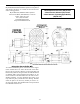
From the bottom of the rotary table, loosen one of the two
socket head cap screws holding the worm housing to the
table base. Lightly tap the housing toward the table with
a plastic mallet to push the
worm a little tighter into
the gear teeth on the table.
When backlash is .2° or less,
retighten the screw.
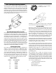
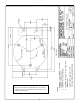
FIGURE 13—The right
angle attachment, P/N 3701
allows the rotary table to
be mounted perpendicular
to the table.
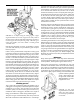
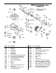
FIGURE 12—A sample setup for cutting a gear. A right
angle attachment (P/N 3701) supports the rotary table in
the 90°position while an adjustable tailstock (P/N 3702) is
used to support the end of the long shaft. A Sherline gear
tooth cutter holder (P/N 3217) holds a custom-ground
1/4" HSS cutter.
-13-