
Instructions


are doing a hole layout, you very seldom can work with
the angles and dimensions on your drawing because of the
cutter diameter.
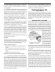
FIGURE 6—Cutter machining outside of part.
FIGURE 7—Cutter machining inside of part.
Figures 6 and 7 show the relation of cutter and part. Start
considering what I refer to as CPR, which is where the center
of the cutter is from the center of the rotary table.
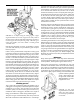
FIGURE 8—This example shows how easy it is to allow
for the cutter diameter using trigonometry.
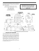
The next problem to be aware of is why the rotary table must
be offset to cut segments. Study Figure 9 and it becomes
obvious that allowing for the cutter diameter at one end of
the segment will not make any correction at the other.
Example: Cutting a Wheel with Spokes
When one of our customers purchases his first metal cutting
tool, it is usually a lathe, and somewhere in that customer’s
mind is a brass canon he has been wanting to build. When
a customer buys his first rotary table, chances are he either
wants to drill hole patterns, which shouldn’t require any
instructions, or he wants to make some kind of wheel with
spokes in it. Therefore, I will describe how to “accurately”
cut a wheel with spokes. I realize that in most cases it is
not necessary to work to this degree of accuracy to do a job
of this nature, but to accurately make a precision part of
this type is what a rotary table is all about. In most cases, I
will leave you to your own common sense as to the depth
of cuts and how much to leave from roughing and finish
cuts. Remember that I have never seen a part scrapped from
taking too light of a cut.
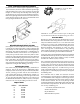
Make an accurate drawing at the start showing offsets
and cutter paths (similar to Figure 10). The offsets can be
calculated as shown in the sample in Figure 10.
REMEMBER...the rotary table center must be precisely
located below the spindle when you start. Only one half of
the segment may be cut from the calculated point, which is
why only one half of the spoke width is considered. Look
at the drawing again and be sure you truly understand why
you can only cut one half of the segment before proceeding,
or your chances for success will be dismal.
Now we have the offsets calculated and the rotary table
“indicated in” in relation to the spindle. We move the
X-axis the amount of the offset, moving the table to the
left. Be sure to consider the backlash, and it may also be
prudent to allow for roughing and finish cuts. Now move
the Y-axis and the Y offset in (towards the column). This
will allow the first half of the segment to be cut so that
it looks like the diagram. Assuming the part is properly
clamped to the rotary table and held in such a way that you
can’t inadvertently cut into the table, it’s time to start. The
example has four equal segments, which means a spoke
will be cut every 90°; therefore, a lot of confusion can be
eliminated if you start with your table at 0° (see Figure 8).
The center of the spokes will now lay out at 0°, 90°, 180°,
and 270°, and the halfway points will be at 45°, 135° etc.
Allowance for the cutter was taken care of when the offsets
were calculated. It is not necessary to calculate the value
of angle “A” or other angles because you are only cutting
half of the segment at a time.
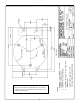
FIGURE 9—Offsetting the rotary table to cut segments.
-11-