
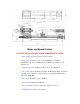
Sherline Mill and Lathe Specifications
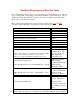


Standard Dimensions of Sherline Tools
If you are making special tooling or a custom accessory for your Sherline tools, this will
save you the trouble of measuring your particular machine to find a dimension, some of
which are actually quite difficult to measure. If you need a dimension not listed here,
please call or write with your request.
Most of the regular specifications can be found by looking at the Lathe and Mill
descriptive pages which have a Specifications List at the end of each.
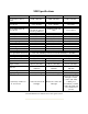
LOCATION DIMENSION
Bed dovetail angle 55.5 degrees*
Lathe bed to spindle centerline 1.75"
Lathe table surface to spindle centerline (calculated) .940"
Headstock spindle nose internal taper #1 Morse
Lathe tailstock internal taper #0 Morse
Headstock spindle external thread 3/4-16
Pulley groove side angle 19°
Table T-slot centerline distance (lathe and mill) 1.5"
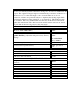
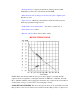
T-slot nominal dimensions**
**Note: The T-slots are extruded into the material. Table
surfaces are machined for flatness, but the slots
themselves require no additional finishing processes.
Slot width, top: .25"
T width, bottom: .40"
Upper slot depth: .10"
T Slot depth: .10"
(Total depth: .20")
Leadscrew thread pitch, inch
(Lathe, mill X and Y axes = 1/4-20, Mill Z axis = 3/8-20)
20 threads per inch or
.050" travel per
revolution (handwheels
divided into 50
increments of .001")
Leadscrew thread pitch, metric
(Lathe, mill X and Y axes = 6.3 x 1 mm, Mill Z = 10 x 1
mm)
1 mm travel per
revolution (handwheels
divided into 100
increments of .01mm)
Leadscrew thread directions
Right-hand: Lathe
crosslide, Mill X-axis
Left-hand: Lathe
leadscrew and tailstock
screw, Mill Y-axis and
Z-axis
*NOTE: This dimension was determined by measuring the extruded bases that were
supplied when we first took over production in the USA from the former Australian